HP 17-bs000 Maintenance and Service Guide - Page 82
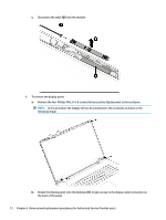
Remove the Phillips PM2.0×5.0 screw
 |
View all HP 17-bs000 manuals
Add to My Manuals
Save this manual to your list of manuals |
Page 82 highlights
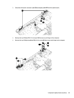
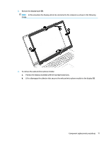
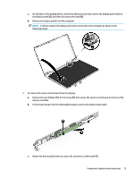
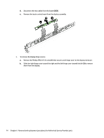
d. Disconnect the two cables from the board (2)(3). e. Remove the touch control board from the display assembly. 6. To remove the display hinge covers: a. Remove the Phillips PM2.0×5.0 screw (1) that secures each hinge cover to the display enclosure. b. Slide the right hinge cover toward the right and the left hinge cover toward the left (2) to remove them from the display. 74 Chapter 6 Removal and replacement procedures for Authorized Service Provider parts
-
 1
1 -
2
-
3
-
4
-
5
-
6
-
7
-
8
-
9
-
10
-
11
-
12
-
13
-
14
-
15
-
16
-
17
-
18
-
19
-
20
-
21
-
22
-
23
-
24
-
25
-
26
-
27
-
28
-
29
-
30
-
31
-
32
-
33
-
34
-
35
-
36
-
37
-
38
-
39
-
40
-
41
-
42
-
43
-
44
-
45
-
46
-
47
-
48
-
49
-
50
-
51
-
52
-
53
-
54
-
55
-
56
-
57
-
58
-
59
-
60
-
61
-
62
-
63
-
64
-
65
-
66
-
67
-
68
-
69
-
70
-
71
-
72
-
73
-
74
-
75
-
76
-
 77
77 -
 78
78 -
 79
79 -
 80
80 -
 81
81 -
 82
82 -
 83
83 -
 84
84 -
 85
85 -
 86
86 -
 87
87 -
88
-
89
-
90
-
91
-
92
-
93
-
94
-
95
-
96
-
97
-
98
-
99
-
100
-
101
-
102
-
103
-
104
-
105
-
106
-
107
-
108
-
109
-
110
-
111
-
112
-
113
-
114
 |
 |
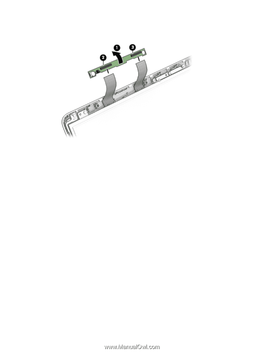
d.
Disconnect the two cables from the board
(2)(3)
.
e.
Remove the touch control board from the display assembly.
6.
To remove the display hinge covers:
a.
Remove the Phillips PM2.0×5.0 screw
(1)
that secures each hinge cover to the display enclosure.
b.
Slide the right hinge cover toward the right and the left hinge cover toward the left
(2)
to remove
them from the display.
74
Chapter 6
Removal and replacement procedures for Authorized Service Provider parts