HP Brocade 8/12c Brocade Fabric OS Troubleshooting and Diagnostics Guide - Sup - Page 120
Checking temperature status, System message log - brocade 8510 hardware reference manual
 |
View all HP Brocade 8/12c manuals
Add to My Manuals
Save this manual to your list of manuals |
Page 120 highlights
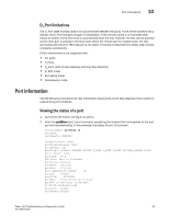
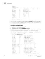
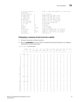
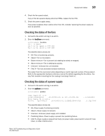
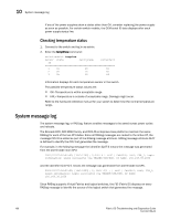
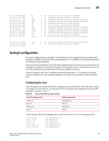
10 System message log If any of the power supplies show a status other than OK, consider replacing the power supply as soon as possible. For certain switch models, the OEM serial ID data displays after each power supply status line. Checking temperature status 1. Connect to the switch and log in as admin. 2. Enter the tempShow command: switch:admin> tempshow Sensor State Centigrade Fahrenheit ID 1 Ok 28 82 2 Ok 16 60 3 Ok 18 64 Information displays for each temperature sensor in the switch. The possible temperature status values are: • OK-Temperature is within acceptable range. • FAIL-Temperature is outside of acceptable range. Damage might occur. Refer to the hardware reference manual for your switch to determine the normal temperature range. System message log The system message log, or RASLog, feature enables messages to be saved across power cycles and reboots. The Brocade DCX, DCX 8510 family, and DCX-4S enterprise-class platforms maintain the same RASlog for each of the two CP blades. Since all RASlog messages are routed to the Active CP, the message CPU ID is added as part of the RASlog message attribute. RASlog message attribute SLOT is defined to identify the CPU that generated the message. For example, in the following message the identifier SLOT 6 means the message was generated from the slot 6 blade main CPU: 2001/01/07-04:03:00, [SEC-1203], 2,SLOT 6 | FFDC | CHASSIS, INFO, C08_1, Login information: Login successful via TELNET/SSH/RSH. IP Addr: 192.168.38.2050 and the identifier SLOT 6/1 means the message was generated from slot 6 blade Co-CPU. 2001/01/07-04:03:00, [SEC-1203], 2, SLOT 6/1 , | FFDC | CHASSIS, INFO, C08_1, Login information: Login successful via TELNET/SSH/RSH. IP Addr: 192.168.38.2050 Since RASlog supports Virtual Fabrics and logical switches, the FID (Fabric ID) displays on every RASlog message to identify the source of the logical switch that generates the message. 100 Fabric OS Troubleshooting and Diagnostics Guide 53-1002150-02
-
 1
1 -
2
-
3
-
4
-
5
-
6
-
7
-
8
-
9
-
10
-
11
-
12
-
13
-
14
-
15
-
16
-
17
-
18
-
19
-
20
-
21
-
22
-
23
-
24
-
25
-
26
-
27
-
28
-
29
-
30
-
31
-
32
-
33
-
34
-
35
-
36
-
37
-
38
-
39
-
40
-
41
-
42
-
43
-
44
-
45
-
46
-
47
-
48
-
49
-
50
-
51
-
52
-
53
-
54
-
55
-
56
-
57
-
58
-
59
-
60
-
61
-
62
-
63
-
64
-
65
-
66
-
67
-
68
-
69
-
70
-
71
-
72
-
73
-
74
-
75
-
76
-
77
-
78
-
79
-
80
-
81
-
82
-
83
-
84
-
85
-
86
-
87
-
88
-
89
-
90
-
91
-
92
-
93
-
94
-
95
-
96
-
97
-
98
-
99
-
100
-
101
-
102
-
103
-
104
-
105
-
106
-
107
-
108
-
109
-
110
-
111
-
112
-
113
-
114
-
 115
115 -
 116
116 -
 117
117 -
 118
118 -
 119
119 -
 120
120 -
 121
121 -
 122
122 -
 123
123 -
 124
124 -
 125
125 -
126
-
127
-
128
-
129
-
130
-
131
-
132
-
133
-
134
-
135
-
136
-
137
-
138
 |
 |