HP Dc5850 Technical Reference Guide: HP Compaq dc5850 Series Business Desktop - Page 52
SATA Interfaces
 |
UPC - 884962022993
View all HP Dc5850 manuals
Add to My Manuals
Save this manual to your list of manuals |
Page 52 highlights
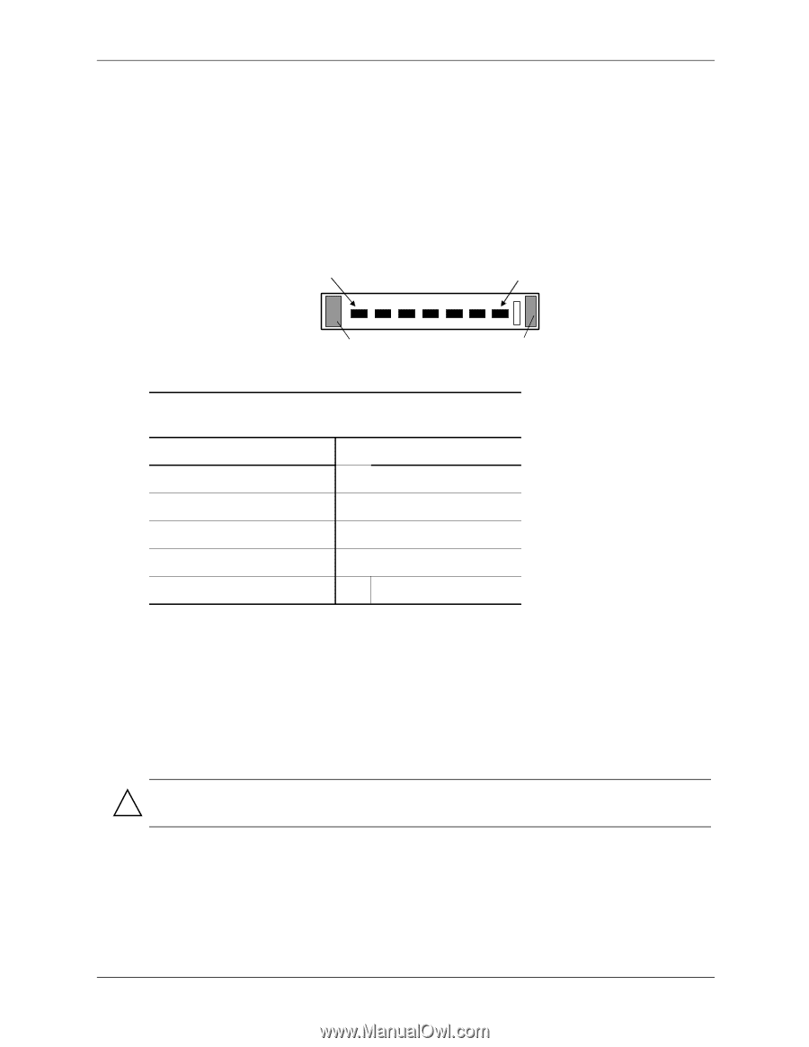
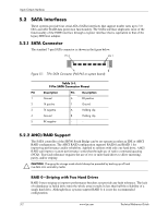
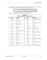
Input/Output Interfaces 5.2 SATA Interfaces These systems provide four serial ATA (SATA) interfaces that support tranfer rates up to 3.0 Gb/s and offer RAID data protection functionality. The SATA interface duplicates most of the functionality of the EIDE interface through a register interface that is equivalent to that of the legacy IDE host adapter. 5.2.1 SATA Connector The standard 7-pin SATA connector is shown in the figure below. Pin 1 Pin 7 A B Figure 5-1. 7-Pin SATA Connector (P60-P63 on system board). Table 5-1. 7-Pin SATA Connector Pinout Pin Description Pin Description 1 Ground 6 RX positive 2 TX positive 7 Ground 3 TX negative A Holding clip 4 Ground B Holding clip 5 RX negative -- -- 5.2.2 AHCI/RAID Support The SATA controller of the SB700 South Bridge can be set operate in either an IDE or AHCI RAID configuration. The AHCI RAID configuration supports RAID 0 and RAID 1 for improving performance and/or reliability. Applied to systems with only one hard drive, AHCI RAID can improve system performance somewhat through use of native command queuing (NCQ). True fault tolerance requires the use of two or more hard drives to allow mirroring, parity, and/or striping. CAUTION: Changing the storage mode should always be preceded by backing up all hard rive data onto secondary media. RAID 0-Striping with Two Hard Drives RAID 0 uses striping to improve performance but does not provide any fault tolerance. The lack of redundancy (a failed drive ruins the whole array) results in less than half the reliability of a single hard drive. Although these systems support RAID 0, it is not the recommended configuration. 5-2 www.hp.com Technical Reference Guide
-
 1
1 -
2
-
3
-
4
-
5
-
6
-
7
-
8
-
9
-
10
-
11
-
12
-
13
-
14
-
15
-
16
-
17
-
18
-
19
-
20
-
21
-
22
-
23
-
24
-
25
-
26
-
27
-
28
-
29
-
30
-
31
-
32
-
33
-
34
-
35
-
36
-
37
-
38
-
39
-
40
-
41
-
42
-
43
-
44
-
45
-
46
-
 47
47 -
 48
48 -
 49
49 -
 50
50 -
 51
51 -
 52
52 -
 53
53 -
 54
54 -
 55
55 -
 56
56 -
 57
57 -
58
-
59
-
60
-
61
-
62
-
63
-
64
-
65
-
66
-
67
-
68
-
69
-
70
-
71
-
72
-
73
-
74
-
75
-
76
-
77
-
78
-
79
-
80
-
81
-
82
-
83
-
84
-
85
-
86
-
87
-
88
-
89
-
90
-
91
-
92
-
93
-
94
-
95
-
96
-
97
-
98
-
99
-
100
-
101
-
102
-
103
-
104
-
105
-
106
-
107
-
108
-
109
-
110
-
111
-
112
-
113
-
114
 |
 |