HP Dc5850 Technical Reference Guide: HP Compaq dc5850 Series Business Desktop - Page 72
Monitor Connectors
 |
UPC - 884962022993
View all HP Dc5850 manuals
Add to My Manuals
Save this manual to your list of manuals |
Page 72 highlights
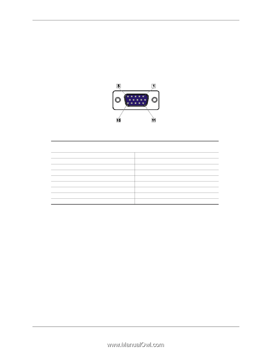
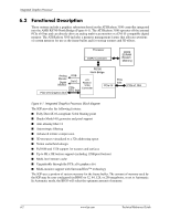
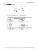
Integrated Graphics Processor 6.4 Monitor Connectors These systems provide an analog VGA connector and a DVI-D connector and can drive both types of monitors simultaneously. 6.4.1 Analog Monitor Connector Figure 6-2 shows the analog VGA connector for attaching an analog video monitor: Figure 6-2. Male DB-15 Analog VGA Monitor Connector, (as viewed from rear of chassis). Pin Signal 1R 2G 3B 4 NC 5 GND 6 R GND 7 G GND 8 B GND Table 6-1. DB-15 Monitor Connector Pinout Description Pin Signal Description Red Analog 9 PWR +5 VDC (fused) [1] Blue Analog 10 GND Ground Green Analog 11 NC Not Connected Not Connected 12 SDA DDC Data Ground 13 HSync Horizontal Sync Red Analog Ground 14 VSync Vertical Sync Blue Analog Ground 15 SCL DDC Clock Green Analog Ground -- -- -- NOTE: [1] Fuse automatically resets when excessive load is removed. 6-4 www.hp.com Technical Reference Guide
-
 1
1 -
2
-
3
-
4
-
5
-
6
-
7
-
8
-
9
-
10
-
11
-
12
-
13
-
14
-
15
-
16
-
17
-
18
-
19
-
20
-
21
-
22
-
23
-
24
-
25
-
26
-
27
-
28
-
29
-
30
-
31
-
32
-
33
-
34
-
35
-
36
-
37
-
38
-
39
-
40
-
41
-
42
-
43
-
44
-
45
-
46
-
47
-
48
-
49
-
50
-
51
-
52
-
53
-
54
-
55
-
56
-
57
-
58
-
59
-
60
-
61
-
62
-
63
-
64
-
65
-
66
-
 67
67 -
 68
68 -
 69
69 -
 70
70 -
 71
71 -
 72
72 -
 73
73 -
 74
74 -
 75
75 -
 76
76 -
 77
77 -
78
-
79
-
80
-
81
-
82
-
83
-
84
-
85
-
86
-
87
-
88
-
89
-
90
-
91
-
92
-
93
-
94
-
95
-
96
-
97
-
98
-
99
-
100
-
101
-
102
-
103
-
104
-
105
-
106
-
107
-
108
-
109
-
110
-
111
-
112
-
113
-
114
 |
 |