HP Dc5850 Technical Reference Guide: HP Compaq dc5850 Series Business Desktop - Page 83
shows pinouts of headers used on the sytem boards.
 |
UPC - 884962022993
View all HP Dc5850 manuals
Add to My Manuals
Save this manual to your list of manuals |
Page 83 highlights
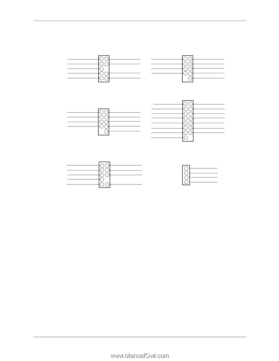
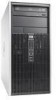
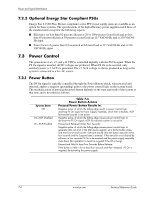
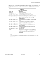
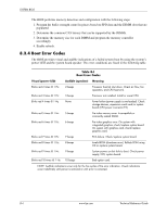
Power and Signal Distribution Figure 7-4 shows pinouts of headers used on the sytem boards. Power Button/LED, HD LED Header P5 HD LED + 1 HD LED - 3 GND5 Pwr Btn 7 Chassis ID0 9 2 PS LED + 4 PS LED - 8 GND 10 Chassis ID1 Front I/O USB Header P5 +5 V fused 1 USB port 8- 3 USB port 8+ 5 GND 7 2 +5 V fused 4 USB port 96 USB port 9+ 8 GND 10 Front USB detect# Media Card Reader USB I/F Header P150 +5 V fused 1 USB port 7- 3 USB port 7+ 5 GND 7 2 +5 V fused 4 USB port 66 USB port 6+ 8 GND 10 not connected Serial Port B Header P52 UART2 DTR- 1 UART2 CTS- 3 UART2 TX DATA 5 GND 7 +5.0V 9 UART2 RTS- 11 UART2 DCD- 13 +12V 15 2 UART2 RX DATA 4 UART2 DSR6 UART2 RI8 GND 10 +3.3V aux 12 Comm B Detect 14 -12V Front Panel Audio Header P23 Mic In Left (Tip) 1 Mic In Right (Sleeve) 3 HP Out Right 5 Sense Send 7 HP Out Left 9 2 Analog GND 4 Front Audio Detect# 6 Sense_1 Return 10 Sense_2 Return Fan Header Header P8, P16 1 GND 2 +12 VDC 3 Fan tach 4 Fan PWM input NOTE: No polarity consideration required for connection to speaker header P6. NC = Not connected Figure 7-4. System Board Header Pinouts Technical Reference Guide www.hp.com 7-9
-
 1
1 -
2
-
3
-
4
-
5
-
6
-
7
-
8
-
9
-
10
-
11
-
12
-
13
-
14
-
15
-
16
-
17
-
18
-
19
-
20
-
21
-
22
-
23
-
24
-
25
-
26
-
27
-
28
-
29
-
30
-
31
-
32
-
33
-
34
-
35
-
36
-
37
-
38
-
39
-
40
-
41
-
42
-
43
-
44
-
45
-
46
-
47
-
48
-
49
-
50
-
51
-
52
-
53
-
54
-
55
-
56
-
57
-
58
-
59
-
60
-
61
-
62
-
63
-
64
-
65
-
66
-
67
-
68
-
69
-
70
-
71
-
72
-
73
-
74
-
75
-
76
-
77
-
 78
78 -
 79
79 -
 80
80 -
 81
81 -
 82
82 -
 83
83 -
 84
84 -
 85
85 -
 86
86 -
 87
87 -
 88
88 -
89
-
90
-
91
-
92
-
93
-
94
-
95
-
96
-
97
-
98
-
99
-
100
-
101
-
102
-
103
-
104
-
105
-
106
-
107
-
108
-
109
-
110
-
111
-
112
-
113
-
114
 |
 |