HP Dc5850 Technical Reference Guide: HP Compaq dc5850 Series Business Desktop - Page 77
MT Power Supply
 |
UPC - 884962022993
View all HP Dc5850 manuals
Add to My Manuals
Save this manual to your list of manuals |
Page 77 highlights
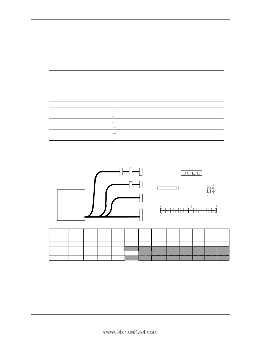
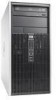
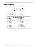
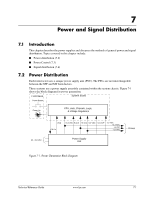
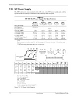
Power and Signal Distribution 7.2.2 MT Power Supply The MT form factor comes standard with a 300-watt, passive-PFC power supply unit with the specifications and cabling as indicated in the following table and figure. Table 7-2. MT 300-Watt Power Supply Unit Specifications Input Line Voltage: 115-230 VAC (auto-ranging) Line Frequency Input (AC) Current +3.3 VDC Output +5.08 VDC Output +5.08 AUX Output +12 VDC Output +12 VDC Output (Vcpu) -12 VDC Output Range or Tolerance Min. Current Max. Surge Loading [1] Current Current [2] 90-264 VAC 47-63 Hz -+ 4 % + 3.3 % + 3.3 % + 5 % + 5 % + 10 % ---0.10 A 0.30 A 0.00 A 0.10 A 0.10 A 0.00 A --6.0 A 16.0 A 19.0 A 2.00 A 11.0 A 11.5 A 0.15 A ---16.0 A 19.0 A 2.00 A 11.0 A 11.5 A 0.15 A Max. Ripple ---50 mV 50 mV 50 mV 120 mV 120 mv 200 mV NOTES: Total continuous output power should not exceed 300 watts. Maximum surge power (
-
 1
1 -
2
-
3
-
4
-
5
-
6
-
7
-
8
-
9
-
10
-
11
-
12
-
13
-
14
-
15
-
16
-
17
-
18
-
19
-
20
-
21
-
22
-
23
-
24
-
25
-
26
-
27
-
28
-
29
-
30
-
31
-
32
-
33
-
34
-
35
-
36
-
37
-
38
-
39
-
40
-
41
-
42
-
43
-
44
-
45
-
46
-
47
-
48
-
49
-
50
-
51
-
52
-
53
-
54
-
55
-
56
-
57
-
58
-
59
-
60
-
61
-
62
-
63
-
64
-
65
-
66
-
67
-
68
-
69
-
70
-
71
-
 72
72 -
 73
73 -
 74
74 -
 75
75 -
 76
76 -
 77
77 -
 78
78 -
 79
79 -
 80
80 -
 81
81 -
 82
82 -
83
-
84
-
85
-
86
-
87
-
88
-
89
-
90
-
91
-
92
-
93
-
94
-
95
-
96
-
97
-
98
-
99
-
100
-
101
-
102
-
103
-
104
-
105
-
106
-
107
-
108
-
109
-
110
-
111
-
112
-
113
-
114
 |
 |