HP Dc5850 Technical Reference Guide: HP Compaq dc5850 Series Business Desktop - Page 61
Universal Serial Bus Interface
 |
UPC - 884962022993
View all HP Dc5850 manuals
Add to My Manuals
Save this manual to your list of manuals |
Page 61 highlights
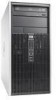
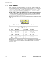
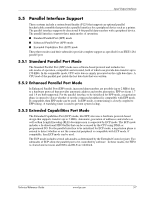
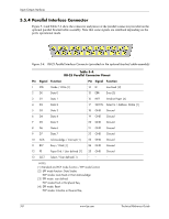
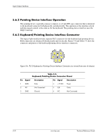
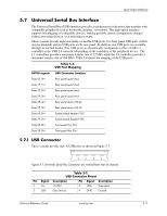
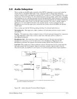
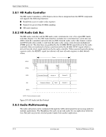
Input/Output Interfaces 5.7 Universal Serial Bus Interface The Universal Serial Bus (USB) interface provides asynchronous/isochronous data transfers with compatible peripherals such as keyboards, printers, or modems. This high-speed interface supports hot-plugging of compatible devices, making possible system configuration changes without powering down or even rebooting systems. These systems provide eight externally-accessible USB ports, two front panel USB ports (which may be disabled) and six USB ports on the rear panel. In addition, twe USB ports are available through an internal header (The USB ports are dynamically configured to either a USB 1.1 controller or the USB 2.0 controller depending on the capability of the peripheral device. The 1.1 controllers provide a maximum transfer rate of 12 Mb/s while the 2.0 controller provides a maximum transfer rate of 480 Mb/s. Table 5-6 shows the mapping of the USB ports. Table 5-6. USB Port Mapping SB700 signals USB Connector Location Data 0P, 0N Rear panel quad stack Data 1P, 1N Rear panel quad stack Data 2P, 2N Rear panel quad stack Data 3P, 3N Rear panel quad stack Data 4P, 4N Rear panel dual w/RJ-45 Data 5P, 5N Rear panel dual w/RJ-45 Data 6P, 6N System board header P150 Data 7P, 7N System board header P150 Data 8P, 8N Front panel thru P24 Data 9P, 9N Front panel thru P24 5.7.1 USB Connector These systems provide type-A USB ports as shown in Figure 5-7. 1 2 3 4 Figure 5-7 Universal Serial Bus Connector (as viewed from rear of chassis) Table 5-7. USB Connector Pinout Pin Signal Description Pin Signal Description 1 Vcc +5 VDC 3 USB+ Data (plus) 2 USB- Data (minus) 4 GND Ground Technical Reference Guide www.hp.com 5-11
-
 1
1 -
2
-
3
-
4
-
5
-
6
-
7
-
8
-
9
-
10
-
11
-
12
-
13
-
14
-
15
-
16
-
17
-
18
-
19
-
20
-
21
-
22
-
23
-
24
-
25
-
26
-
27
-
28
-
29
-
30
-
31
-
32
-
33
-
34
-
35
-
36
-
37
-
38
-
39
-
40
-
41
-
42
-
43
-
44
-
45
-
46
-
47
-
48
-
49
-
50
-
51
-
52
-
53
-
54
-
55
-
 56
56 -
 57
57 -
 58
58 -
 59
59 -
 60
60 -
 61
61 -
 62
62 -
 63
63 -
 64
64 -
 65
65 -
 66
66 -
67
-
68
-
69
-
70
-
71
-
72
-
73
-
74
-
75
-
76
-
77
-
78
-
79
-
80
-
81
-
82
-
83
-
84
-
85
-
86
-
87
-
88
-
89
-
90
-
91
-
92
-
93
-
94
-
95
-
96
-
97
-
98
-
99
-
100
-
101
-
102
-
103
-
104
-
105
-
106
-
107
-
108
-
109
-
110
-
111
-
112
-
113
-
114
 |
 |