HP Dc5850 Technical Reference Guide: HP Compaq dc5850 Series Business Desktop - Page 63
Audio Subsystem - 4 beeps
 |
UPC - 884962022993
View all HP Dc5850 manuals
Add to My Manuals
Save this manual to your list of manuals |
Page 63 highlights
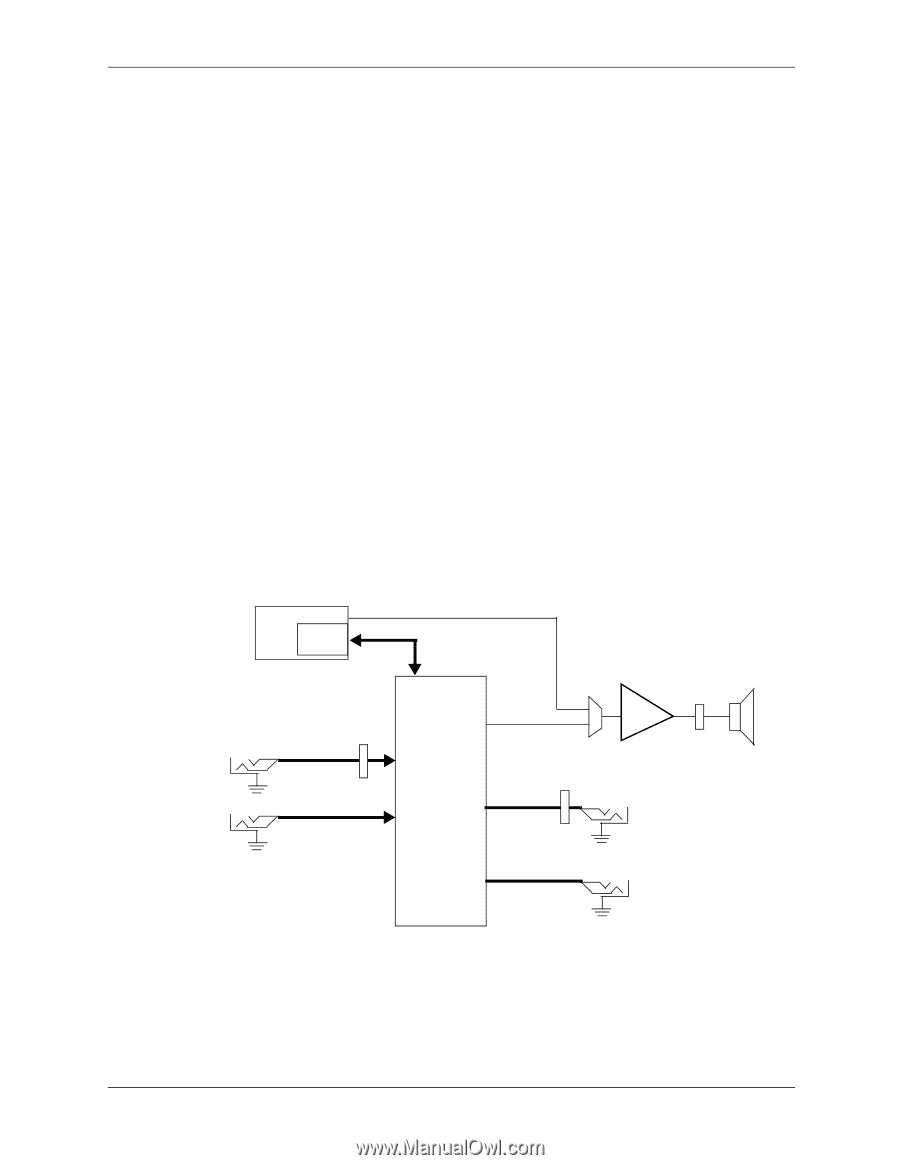
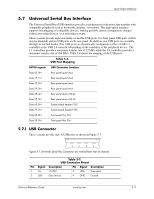
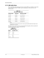
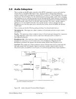
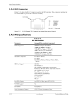
Input/Output Interfaces 5.8 Audio Subsystem These systems use the HD audio controller of the SB700 component to access and control an Analog Devices AD1884A HD Audio Codec, which provides 2-channel high definition analog-to-digital (ADC) and digital-to-analog (DAC) conversions. A block diagram of the audio subsystem is shown in Figure 5-8. All control functions such as volume, audio source selection, and sampling rate are controlled through software through the HD Audio Interface of the SB700 component. Control data and digital audio streams (record and playback) are transferred between the SB700 and the Audio Codec over the HD Audio Interface. The codec's speaker output is applied to a 1.5-watt amplifier that drives the internal speaker. A device plugged into the Headphone jack or the line input jack is sensed by the system, which will inhibit the Speaker Audio signal. These systems provide the following analog interfaces for external audio devices: Microphone In-This input uses a three-conductor 1/8-inch mini-jack that accepts a stereo microphone. Line In-This input uses a three-conductor (stereo) 1/8-inch mini-jack designed for connection of a high-impedance audio source such as a tape deck. This jack can be re-tasked to a Microphone In function. Headphones Out-This input uses a three-conductor (stereo) 1/8-inch mini-jack that is designed for connecting a set of 32-ohm (nom.) stereo headphones. Plugging into the Headphones jack mutes the signal to the internal speaker and the Line Out jack as well. Line Out-This output uses a three-conductor (stereo) 1/8-inch mini-jack for connecting left and right channel line-level signals. Typical connections include a tape recorder's Line In (Record In) jacks, an amplifier's Line In jacks, or to powered speakers that contain amplifiers. Front Panel Mic In Rear Panel Line In [1] SB700 HD Audio Interface PC Beep HD Audio I/F Header P23 Mic Audio (L/R) Line Audio (L/R) Speaker Audio (mono) AD1884A HD Audio Codec Header Headphone P23 Audio (L/R) Line Audio Out (L/R) Audio Amp Header P6 Front Panel Headphones Out Rear Panel Line Out NOTES: L/R = Separate left and right channels (stereo). L+R = Combined left and right channels (mono). [1] Can be re-configured as Microphone In Figure 5-8. Audio Subsystem Functional Block Diagram Technical Reference Guide www.hp.com 5-13
-
 1
1 -
2
-
3
-
4
-
5
-
6
-
7
-
8
-
9
-
10
-
11
-
12
-
13
-
14
-
15
-
16
-
17
-
18
-
19
-
20
-
21
-
22
-
23
-
24
-
25
-
26
-
27
-
28
-
29
-
30
-
31
-
32
-
33
-
34
-
35
-
36
-
37
-
38
-
39
-
40
-
41
-
42
-
43
-
44
-
45
-
46
-
47
-
48
-
49
-
50
-
51
-
52
-
53
-
54
-
55
-
56
-
57
-
 58
58 -
 59
59 -
 60
60 -
 61
61 -
 62
62 -
 63
63 -
 64
64 -
 65
65 -
 66
66 -
 67
67 -
 68
68 -
69
-
70
-
71
-
72
-
73
-
74
-
75
-
76
-
77
-
78
-
79
-
80
-
81
-
82
-
83
-
84
-
85
-
86
-
87
-
88
-
89
-
90
-
91
-
92
-
93
-
94
-
95
-
96
-
97
-
98
-
99
-
100
-
101
-
102
-
103
-
104
-
105
-
106
-
107
-
108
-
109
-
110
-
111
-
112
-
113
-
114
 |
 |