HP ENVY 14t-2000 HP ENVY 14 Notebook PC - Maintenance and Service Guide - Page 65
Remove the Phillips PM2.0×2.82 screw, base enclosure.
 |
View all HP ENVY 14t-2000 manuals
Add to My Manuals
Save this manual to your list of manuals |
Page 65 highlights
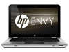
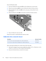
3. Disconnect the power from the computer by first unplugging the power cord from the AC outlet and then unplugging the AC adapter from the computer. 4. Remove the battery cover and battery (see Battery on page 36), and then remove the following components: a. Hard drive (see Mass storage device on page 38) b. Memory module/wireless module compartment cover (see WLAN module on page 41) c. Top cover (see Top cover on page 49) Remove the solid-state drive connector board: 1. Disconnect the Bluetooth module cable (1) from the solid-state drive connector board. 2. Release the ZIF connector to which the solid-state drive connector board cable is attached, and then disconnect the cable (2) from the system board. 3. Release the grounding tape (3) that secures the solid-state drive connector board cable to the base enclosure. 4. Remove the Phillips PM2.0×2.82 screw (4) that secures the solid-state drive connector board to the base enclosure. 5. Remove the solid-state drive connector board (5) and cable. Reverse this procedure to install the solid-state drive connector board and cable. Component replacement procedures 57
-
 1
1 -
2
-
3
-
4
-
5
-
6
-
7
-
8
-
9
-
10
-
11
-
12
-
13
-
14
-
15
-
16
-
17
-
18
-
19
-
20
-
21
-
22
-
23
-
24
-
25
-
26
-
27
-
28
-
29
-
30
-
31
-
32
-
33
-
34
-
35
-
36
-
37
-
38
-
39
-
40
-
41
-
42
-
43
-
44
-
45
-
46
-
47
-
48
-
49
-
50
-
51
-
52
-
53
-
54
-
55
-
56
-
57
-
58
-
59
-
 60
60 -
 61
61 -
 62
62 -
 63
63 -
 64
64 -
 65
65 -
 66
66 -
 67
67 -
 68
68 -
 69
69 -
 70
70 -
71
-
72
-
73
-
74
-
75
-
76
-
77
-
78
-
79
-
80
-
81
-
82
-
83
-
84
-
85
-
86
-
87
-
88
-
89
-
90
-
91
-
92
-
93
-
94
-
95
-
96
-
97
-
98
-
99
-
100
-
101
-
102
-
103
-
104
-
105
 |
 |
