HP ENVY 14t-2000 HP ENVY 14 Notebook PC - Maintenance and Service Guide - Page 69
from the alignment clip built into the base enclosure., Remove the power connector cable
 |
View all HP ENVY 14t-2000 manuals
Add to My Manuals
Save this manual to your list of manuals |
Page 69 highlights
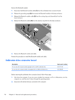
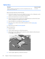
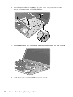
Remove the power connector cable: 1. Disconnect the power extension cable (1) from the battery connector board. 2. Release the power extension cord (2) from the system board. (The power extension cord is attached to the system board with double-sided tape.) 3. Disconnect the power connector cable (3) from the system board. 4. Release the power connector (4) from the alignment clip built into the base enclosure. 5. Remove the power connector cable. Reverse this procedure to install the power connector cable. Component replacement procedures 61
-
 1
1 -
2
-
3
-
4
-
5
-
6
-
7
-
8
-
9
-
10
-
11
-
12
-
13
-
14
-
15
-
16
-
17
-
18
-
19
-
20
-
21
-
22
-
23
-
24
-
25
-
26
-
27
-
28
-
29
-
30
-
31
-
32
-
33
-
34
-
35
-
36
-
37
-
38
-
39
-
40
-
41
-
42
-
43
-
44
-
45
-
46
-
47
-
48
-
49
-
50
-
51
-
52
-
53
-
54
-
55
-
56
-
57
-
58
-
59
-
60
-
61
-
62
-
63
-
 64
64 -
 65
65 -
 66
66 -
 67
67 -
 68
68 -
 69
69 -
 70
70 -
 71
71 -
 72
72 -
 73
73 -
 74
74 -
75
-
76
-
77
-
78
-
79
-
80
-
81
-
82
-
83
-
84
-
85
-
86
-
87
-
88
-
89
-
90
-
91
-
92
-
93
-
94
-
95
-
96
-
97
-
98
-
99
-
100
-
101
-
102
-
103
-
104
-
105
 |
 |

Remove the power connector cable:
1.
Disconnect the power extension cable
(1)
from the battery connector board.
2.
Release the power extension cord
(2)
from the system board. (The power extension cord is
attached to the system board with double-sided tape.)
3.
Disconnect the power connector cable
(3)
from the system board.
4.
Release the power connector
(4)
from the alignment clip built into the base enclosure.
5.
Remove the power connector cable.
Reverse this procedure to install the power connector cable.
Component replacement procedures
61