HP ENVY 14t-2000 HP ENVY 14 Notebook PC - Maintenance and Service Guide - Page 70
System board, defective system board and installed on the replacement system board
 |
View all HP ENVY 14t-2000 manuals
Add to My Manuals
Save this manual to your list of manuals |
Page 70 highlights
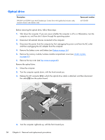
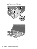
System board NOTE: The system board spare part kit includes replacement thermal material. Replacement thermal material is also available in the Thermal Material Kit, spare part number 634366-001. Description System board equipped with Intel 6 series express chipset, Intel HM65 PCH, Radeon HD 6630M graphics subsystem with 1024-MB of discrete video memory Spare part number 654173-001 Before removing the system board, follow these steps: 1. Shut down the computer. If you are unsure whether the computer is off or in Hibernation, turn the computer on, and then shut it down through the operating system. 2. Disconnect all external devices connected to the computer. 3. Disconnect the power from the computer by first unplugging the power cord from the AC outlet and then unplugging the AC adapter from the computer. 4. Remove the battery cover and battery (see Battery on page 36). 5. Remove the hard drive (see Mass storage device on page 38). 6. Remove the memory module/wireless module compartment cover (see WLAN module on page 41). 7. Disconnect the battery charger board ribbon cable from the system board (see Battery connector board on page 47). 8. Remove the top cover (see Top cover on page 49). 9. Disconnect the optical drive cable from the system board (see Optical drive on page 58). When replacing the system board, be sure that the following components are removed from the defective system board and installed on the replacement system board: ● WLAN module (see WLAN module on page 41) ● RTC battery (see RTC battery on page 44) ● Memory module (see Memory module on page 46) ● Fan/heat sink assembly (see Fan/heat sink assembly on page 65) ● Processor (see Processor on page 67) Remove the system board: 1. Release the ZIF connector to which the audio/USB board cable is attached, and then disconnect the cable (1) from the system board. 62 Chapter 4 Removal and replacement procedures
-
 1
1 -
2
-
3
-
4
-
5
-
6
-
7
-
8
-
9
-
10
-
11
-
12
-
13
-
14
-
15
-
16
-
17
-
18
-
19
-
20
-
21
-
22
-
23
-
24
-
25
-
26
-
27
-
28
-
29
-
30
-
31
-
32
-
33
-
34
-
35
-
36
-
37
-
38
-
39
-
40
-
41
-
42
-
43
-
44
-
45
-
46
-
47
-
48
-
49
-
50
-
51
-
52
-
53
-
54
-
55
-
56
-
57
-
58
-
59
-
60
-
61
-
62
-
63
-
64
-
 65
65 -
 66
66 -
 67
67 -
 68
68 -
 69
69 -
 70
70 -
 71
71 -
 72
72 -
 73
73 -
 74
74 -
 75
75 -
76
-
77
-
78
-
79
-
80
-
81
-
82
-
83
-
84
-
85
-
86
-
87
-
88
-
89
-
90
-
91
-
92
-
93
-
94
-
95
-
96
-
97
-
98
-
99
-
100
-
101
-
102
-
103
-
104
-
105
 |
 |
