HP ENVY 15-bp100 Maintenance and Service Guide 1 - Page 47
Card reader board
 |
View all HP ENVY 15-bp100 manuals
Add to My Manuals
Save this manual to your list of manuals |
Page 47 highlights
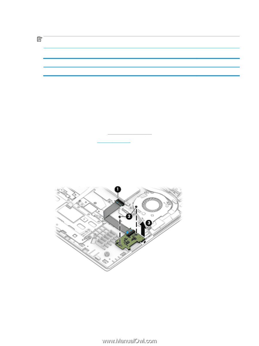
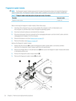
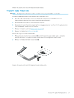
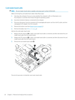
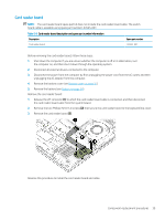
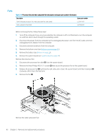
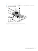
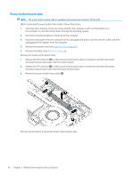
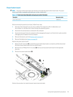
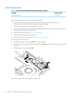
Card reader board NOTE: The card reader board spare part kit does not include the card reader board cable. The switch board cable is available using spare part number L53535-001. Table 5-8 Card reader board description and spare part number information Description Spare part number Card reader board L53553-001 Before removing the card reader board, follow these steps: 1. Shut down the computer. If you are unsure whether the computer is off or in Hibernation, turn the computer on, and then shut it down through the operating system. 2. Disconnect all external devices connected to the computer. 3. Disconnect the power from the computer by first unplugging the power cord from the AC outlet, and then unplugging the AC adapter from the computer. 4. Remove the bottom cover (see Bottom cover on page 25). 5. Remove the battery (see Battery on page 26). Remove the card reader board: 1. Release the ZIF connector (1) to which the card reader board cable is connected, and then disconnect the card reader board cable from the system board. 2. Remove the two Phillips M2.0×3.0 screws (2) that secure the card reader board to the keyboard/top cover. 3. Remove the card reader board (3). Reverse this procedure to install the card reader board and cable. Component replacement procedures 39
-
 1
1 -
2
-
3
-
4
-
5
-
6
-
7
-
8
-
9
-
10
-
11
-
12
-
13
-
14
-
15
-
16
-
17
-
18
-
19
-
20
-
21
-
22
-
23
-
24
-
25
-
26
-
27
-
28
-
29
-
30
-
31
-
32
-
33
-
34
-
35
-
36
-
37
-
38
-
39
-
40
-
41
-
 42
42 -
 43
43 -
 44
44 -
 45
45 -
 46
46 -
 47
47 -
 48
48 -
 49
49 -
 50
50 -
 51
51 -
 52
52 -
53
-
54
-
55
-
56
-
57
-
58
-
59
-
60
-
61
-
62
-
63
-
64
-
65
-
66
-
67
-
68
-
69
-
70
-
71
-
72
-
73
-
74
-
75
-
76
-
77
-
78
-
79
-
80
-
81
-
82
 |
 |