HP ENVY 15-bp100 Maintenance and Service Guide 1 - Page 55
System board
 |
View all HP ENVY 15-bp100 manuals
Add to My Manuals
Save this manual to your list of manuals |
Page 55 highlights
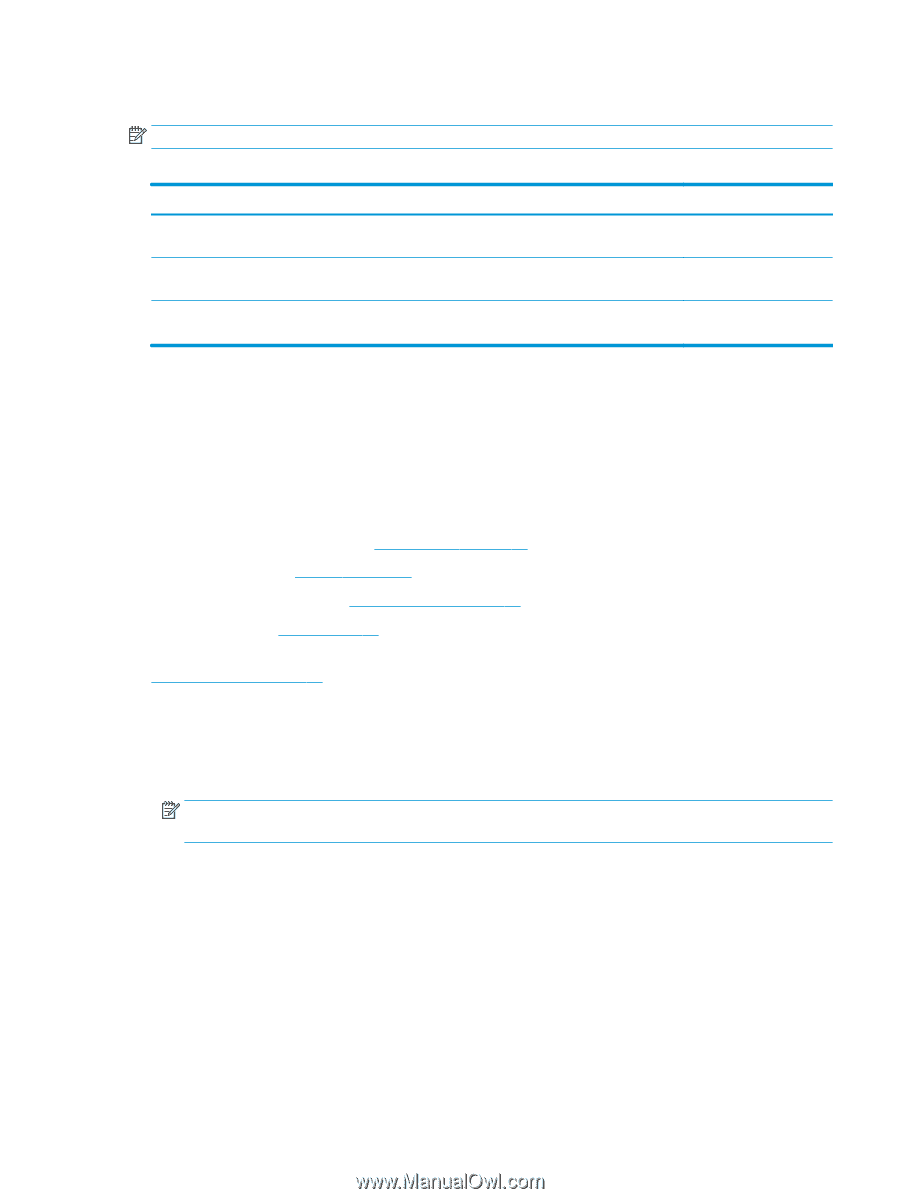
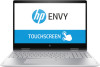
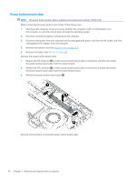
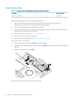
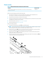
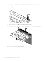
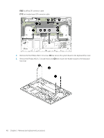
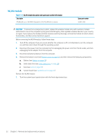
System board NOTE: The system board spare part kit includes a processor and replacement thermal material. Table 5-13 System board description and spare part number information Description Spare part number Equipped with an AMD Ryzen7-3700U 2.3-GHz (turbo up to 4.0-GHz) processor (2400-MHz FSB, 6-MB L2/L3 cache, quad core, 25 W cTDP) and the Windows 10 operating system Equipped with an AMD Ryzen5-3500U 2.1-GHz (turbo up to 3.7-GHz) processor (2400-MHz FSB, 6-MB L2/L3 cache, quad core, 25 W cTDP) and the Windows 10 operating system Equipped with an AMD Ryzen3-3300U 2.1-GHz (turbo up to 3.5-GHz) processor (2400-MHz FSB, 6-MB L2/L3 cache, quad core, 25 W) and the Windows 10 operating system L53875-601 L53874-601 L53873-601 Before removing the system board, follow these steps: 1. Shut down the computer. If you are unsure whether the computer is off or in Hibernation, turn the computer on, and then shut it down through the operating system. 2. Disconnect all external devices connected to the computer. 3. Disconnect the power from the computer by first unplugging the power cord from the AC outlet, and then unplugging the AC adapter from the computer. 4. Remove the bottom cover (see Bottom cover on page 25), and then remove the following components: a. Battery (see Battery on page 26) b. Solid-state drive (see Solid-state drive on page 28) c. Fans (see Fans on page 40) When replacing the system board, be sure to remove the memory module shield and memory module (see Memory module on page 29) from the defective system board and install them on the replacement system board. Remove the system board: 1. Disconnect the following cables from the system board: (1) WLAN antenna cables NOTE: The #1/white WLAN antenna cable connects to the WLAN module "#1/Main" terminal. The #2/ black WLAN antenna cable connects to the WLAN module "#2/Aux" terminal. (2) Webcam/microphone module ZIF connector cable (3) Display panel ZIF connector cable (4) Power button board ZIF connector cable (5) Speaker cable (6) Power connector cable (7) Switch board ZIF connector cable (8) Keyboard backlight ZIF connector cable (9) Keyboard ZIF connector cable Component replacement procedures 47
-
 1
1 -
2
-
3
-
4
-
5
-
6
-
7
-
8
-
9
-
10
-
11
-
12
-
13
-
14
-
15
-
16
-
17
-
18
-
19
-
20
-
21
-
22
-
23
-
24
-
25
-
26
-
27
-
28
-
29
-
30
-
31
-
32
-
33
-
34
-
35
-
36
-
37
-
38
-
39
-
40
-
41
-
42
-
43
-
44
-
45
-
46
-
47
-
48
-
49
-
 50
50 -
 51
51 -
 52
52 -
 53
53 -
 54
54 -
 55
55 -
 56
56 -
 57
57 -
 58
58 -
 59
59 -
 60
60 -
61
-
62
-
63
-
64
-
65
-
66
-
67
-
68
-
69
-
70
-
71
-
72
-
73
-
74
-
75
-
76
-
77
-
78
-
79
-
80
-
81
-
82
 |
 |