HP ENVY 15-bp100 Maintenance and Service Guide 1 - Page 53
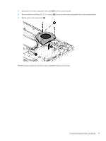
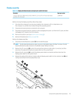
Display assembly, black WLAN antenna cable connects to the WLAN module #2/Aux terminal.
 |
View all HP ENVY 15-bp100 manuals
Add to My Manuals
Save this manual to your list of manuals |
Page 53 highlights
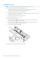
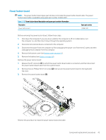
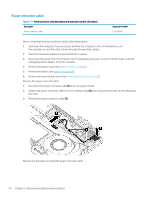
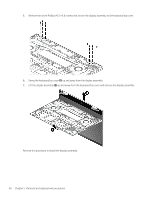
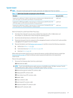
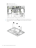
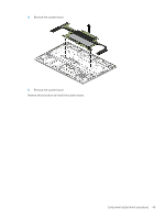
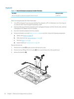
Display assembly Table 5-12 Display assembly description and spare part number information Description 15.6-inch, FHD (1920×1080), AntiGlare, WLED, UWVA, 45, 220 nits, eDP, slim TouchScreen display assembly with narrow bezel Spare part number L53868-001 Before removing the display assembly, follow these steps: 1. Shut down the computer. If you are unsure whether the computer is off or in Hibernation, turn the computer on, and then shut it down through the operating system. 2. Disconnect all external devices connected to the computer. 3. Disconnect the power from the computer by first unplugging the power cord from the AC outlet, and then unplugging the AC adapter from the computer. 4. Remove the bottom cover (see Bottom cover on page 25). 5. Remove the battery (see Battery on page 26). Remove the display assembly: 1. Disconnect the WLAN antenna cables (1) from the WLAN module. NOTE: The #1/white WLAN antenna cable connects to the WLAN module "#1/Main" terminal. The #2/ black WLAN antenna cable connects to the WLAN module "#2/Aux" terminal. 2. Release the ZIF connector (2) to which the webcam/microphone module cable is connected, and then disconnect the webcam/microphone module cable from the system board. 3. Release the ZIF connector (3) to which the display panel cable is connected, and then disconnect the display panel cable from the system board. 4. Release the webcam/microphone module cable and display panel cable from the retention clips (4) and routing channel built into the keyboard/top cover. Component replacement procedures 45
-
 1
1 -
2
-
3
-
4
-
5
-
6
-
7
-
8
-
9
-
10
-
11
-
12
-
13
-
14
-
15
-
16
-
17
-
18
-
19
-
20
-
21
-
22
-
23
-
24
-
25
-
26
-
27
-
28
-
29
-
30
-
31
-
32
-
33
-
34
-
35
-
36
-
37
-
38
-
39
-
40
-
41
-
42
-
43
-
44
-
45
-
46
-
47
-
 48
48 -
 49
49 -
 50
50 -
 51
51 -
 52
52 -
 53
53 -
 54
54 -
 55
55 -
 56
56 -
 57
57 -
 58
58 -
59
-
60
-
61
-
62
-
63
-
64
-
65
-
66
-
67
-
68
-
69
-
70
-
71
-
72
-
73
-
74
-
75
-
76
-
77
-
78
-
79
-
80
-
81
-
82
 |
 |