HP ENVY TouchSmart 14-k020us HP Envy 14 Sleekbook - Maintenance and Service Gu - Page 83
from the bottom corners, Remove the 2 screw covers
 |
View all HP ENVY TouchSmart 14-k020us manuals
Add to My Manuals
Save this manual to your list of manuals |
Page 83 highlights
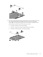
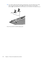
6. Remove the fan (see Fan on page 55). 7. Remove the card reader board (see Card reader board on page 54). 8. Remove the system board (see System board on page 57). Remove the display panel: 1. Remove the 3 Phillips PM2.5×5.5 screws from the hinges (2 from the left, 1 from the right hinge) (1). 2. Remove the Phillips PM2.5×3.5 screw from right hinge (2). 3. Rotate both hinges to the open position (3). 4. Lift the computer up to an angle (4), and then pull the display assembly away from the computer (5). 5. Remove the 2 screw covers (1) and the 2 Phillips PM2.0×2.5 screws (2) from the bottom corners of the bezel. 6. Loosen the top edge of the plastic bezel cover (3) from all four sides of the display panel. Component replacement procedures 75
-
 1
1 -
2
-
3
-
4
-
5
-
6
-
7
-
8
-
9
-
10
-
11
-
12
-
13
-
14
-
15
-
16
-
17
-
18
-
19
-
20
-
21
-
22
-
23
-
24
-
25
-
26
-
27
-
28
-
29
-
30
-
31
-
32
-
33
-
34
-
35
-
36
-
37
-
38
-
39
-
40
-
41
-
42
-
43
-
44
-
45
-
46
-
47
-
48
-
49
-
50
-
51
-
52
-
53
-
54
-
55
-
56
-
57
-
58
-
59
-
60
-
61
-
62
-
63
-
64
-
65
-
66
-
67
-
68
-
69
-
70
-
71
-
72
-
73
-
74
-
75
-
76
-
77
-
 78
78 -
 79
79 -
 80
80 -
 81
81 -
 82
82 -
 83
83 -
 84
84 -
 85
85 -
 86
86 -
 87
87 -
 88
88 -
89
-
90
-
91
-
92
-
93
-
94
-
95
-
96
-
97
-
98
-
99
-
100
-
101
-
102
-
103
-
104
-
105
-
106
-
107
-
108
-
109
-
110
 |
 |
