HP ENVY TouchSmart m6-k125dx HP ENVY m6 Sleekbook HP ENVY Touchsmart m6 SleekB - Page 45
WLAN module, Disconnect all external devices connected to the computer.
 |
View all HP ENVY TouchSmart m6-k125dx manuals
Add to My Manuals
Save this manual to your list of manuals |
Page 45 highlights
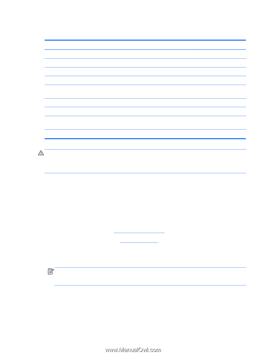
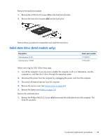
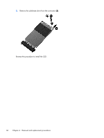
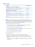
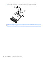
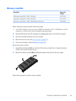
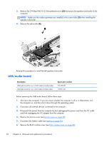
WLAN module Description Spare part number WLAN module for use in both Intel and AMD models: Ralink Wireless + Bluetooth combo w/ *2 antennas (802.11 b/g/n, Bluetooth 4.0) 690020-005 Qualcomm QCA9565 802.11bgn 1x1 Wi-Fi + BT4.0 Combo Adapter 733476-001 WLAN module for use only in Intel models: Intel Centrino® Wireless-N 1030 + Bluetooth combo w/ *2 antennas (802.11 b/g/n, Bluetooth 3.0) 670290-005 Mediatek 7630E 802.11 b/g/n 11 WiFi and Bluetooth 4.0 Combo Adapter 710418-005 Intel Dual Band Wireless-AC 3160 802.11 a/b/g/n/ac (1x1) WiFi with Bluetooth 4.0 combo 710662-001 Intel Centrino® Wireless-N 2230 + Bluetooth combo w/ *2 antennas (802.11 b/g/n, Bluetooth 4.0) 717384-005 Broadcom 4352 + Bluetooth combo w/ *2 antennas (802.11 a/b/g/n, Bluetooth 4.0 724935-005 CAUTION: To prevent an unresponsive system, replace the wireless module only with a wireless module authorized for use in the computer by the governmental agency that regulates wireless devices in your country or region. If you replace the module and then receive a warning message, remove the module to restore device functionality, and then contact technical support. Before removing the WLAN module, follow these steps: 1. Shut down the computer. If you are unsure whether the computer is off or in Hibernation, turn the computer on, and then shut it down through the operating system. 2. Disconnect all external devices connected to the computer. 3. Disconnect the power from the computer by first unplugging the power cord from the AC outlet and then unplugging the AC adapter from the computer. 4. Remove the service cover (see Service cover on page 30). 5. Disconnect the battery cable (see Battery on page 32). Remove the WLAN module: 1. Disconnect the #1 and #2 WLAN antenna cables from the WLAN module (1). NOTE: The #1 WLAN antenna white cable is connected to the WLAN module #1 main terminal. The #2 WLAN antenna black cable is connected to the WLAN module #2 auxiliary terminal. 2. Remove the 2 PM 2.0×3.0 screws (2) that secure the WLAN module to the computer. (The WLAN module tilts up.) Component replacement procedures 37
-
 1
1 -
2
-
3
-
4
-
5
-
6
-
7
-
8
-
9
-
10
-
11
-
12
-
13
-
14
-
15
-
16
-
17
-
18
-
19
-
20
-
21
-
22
-
23
-
24
-
25
-
26
-
27
-
28
-
29
-
30
-
31
-
32
-
33
-
34
-
35
-
36
-
37
-
38
-
39
-
 40
40 -
 41
41 -
 42
42 -
 43
43 -
 44
44 -
 45
45 -
 46
46 -
 47
47 -
 48
48 -
 49
49 -
 50
50 -
51
-
52
-
53
-
54
-
55
-
56
-
57
-
58
-
59
-
60
-
61
-
62
-
63
-
64
-
65
-
66
-
67
-
68
-
69
-
70
-
71
-
72
-
73
-
74
-
75
-
76
-
77
-
78
-
79
-
80
-
81
-
82
-
83
-
84
-
85
-
86
-
87
-
88
-
89
-
90
-
91
-
92
-
93
-
94
-
95
-
96
 |
 |