HP ENVY TouchSmart m6-k125dx HP ENVY m6 Sleekbook HP ENVY Touchsmart m6 SleekB - Page 72
from the bottom of the display panel assembly.
 |
View all HP ENVY TouchSmart m6-k125dx manuals
Add to My Manuals
Save this manual to your list of manuals |
Page 72 highlights
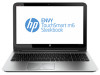
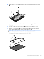
4. Lift the computer up to an angle (4), and then pull the display assembly away from the computer (5). 5. To separate the display enclosure, remove the 2 screw covers (1) and 2 silver Phillips PM 2.5×3.0 screws (2) from the bottom of the display panel assembly. 6. Lift the bottom of the display panel assembly upward to disengage it from the display enclosure (3), and then lift the display panel assembly up and away from the enclosure (4). 64 Chapter 4 Removal and replacement procedures
-
 1
1 -
2
-
3
-
4
-
5
-
6
-
7
-
8
-
9
-
10
-
11
-
12
-
13
-
14
-
15
-
16
-
17
-
18
-
19
-
20
-
21
-
22
-
23
-
24
-
25
-
26
-
27
-
28
-
29
-
30
-
31
-
32
-
33
-
34
-
35
-
36
-
37
-
38
-
39
-
40
-
41
-
42
-
43
-
44
-
45
-
46
-
47
-
48
-
49
-
50
-
51
-
52
-
53
-
54
-
55
-
56
-
57
-
58
-
59
-
60
-
61
-
62
-
63
-
64
-
65
-
66
-
 67
67 -
 68
68 -
 69
69 -
 70
70 -
 71
71 -
 72
72 -
 73
73 -
 74
74 -
 75
75 -
 76
76 -
 77
77 -
78
-
79
-
80
-
81
-
82
-
83
-
84
-
85
-
86
-
87
-
88
-
89
-
90
-
91
-
92
-
93
-
94
-
95
-
96
 |
 |
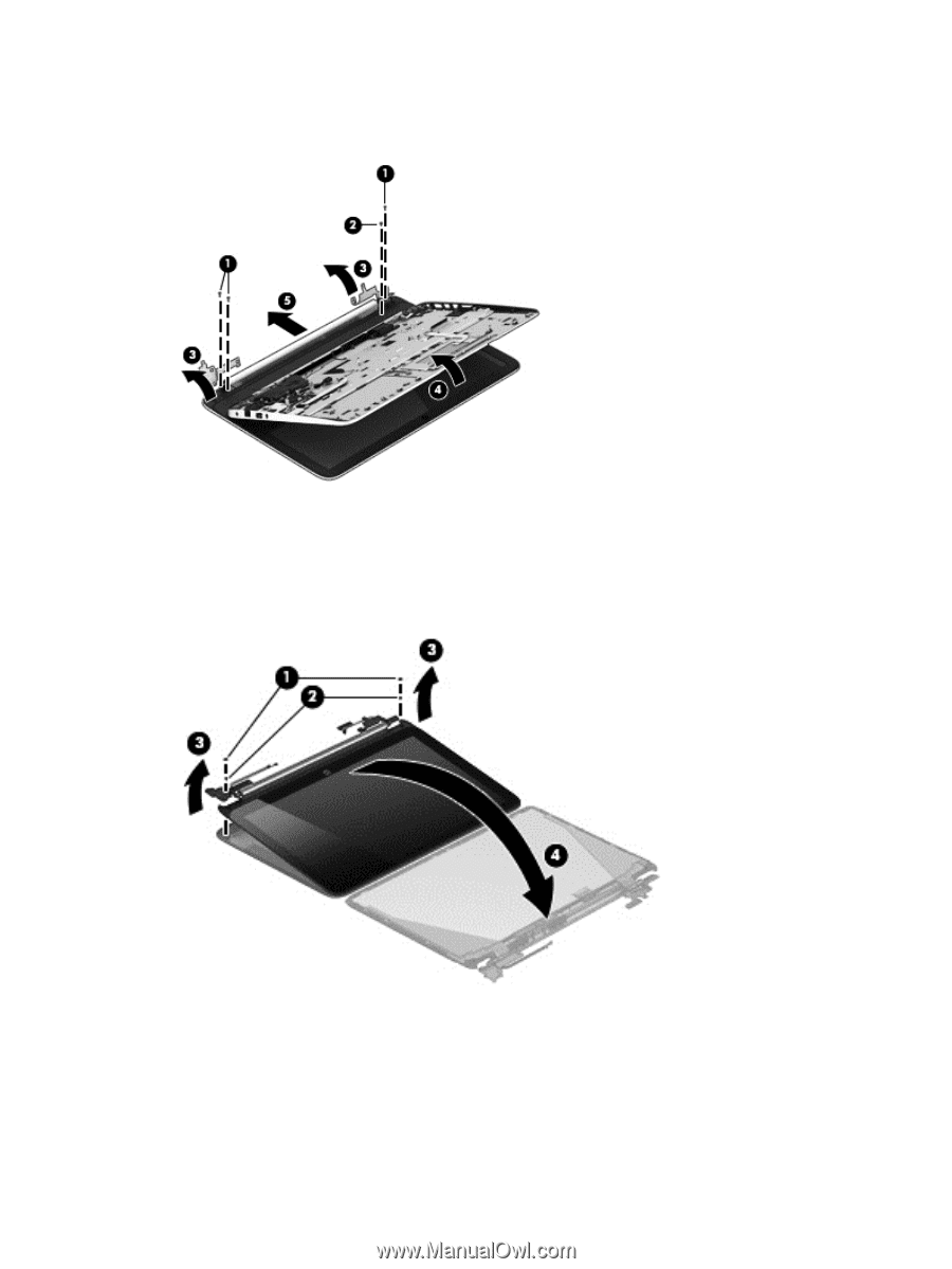
4.
Lift the computer up to an angle
(4)
, and then pull the display assembly away from the computer
(5)
.
5.
To separate the display enclosure, remove the 2 screw covers
(1)
and 2 silver Phillips PM
2.5×3.0 screws
(2)
from the bottom of the display panel assembly.
6.
Lift the bottom of the display panel assembly upward to disengage it from the display enclosure
(3)
, and then lift the display panel assembly up and away from the enclosure
(4)
.
64
Chapter 4
Removal and replacement procedures