HP ENVY TouchSmart m6-k125dx HP ENVY m6 Sleekbook HP ENVY Touchsmart m6 SleekB - Page 55
System board, When replacing the system board
 |
View all HP ENVY TouchSmart m6-k125dx manuals
Add to My Manuals
Save this manual to your list of manuals |
Page 55 highlights
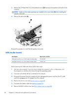
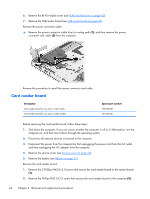
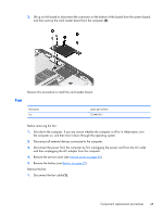
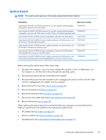
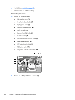
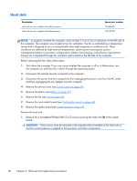
System board NOTE: The system board spare part kit includes replacement thermal material. Description Spare part number System board with AMD A10-5745M processor for use with computer models equipped with graphics subsystem with UMA memory 725462-001 System board with AMD A10-5745M processor for use with computer models equipped 725462-501 with graphics subsystem with UMA memory and the Windows 8 Standard operating system System board with Intel i5-4200U processor and graphics subsystem with UMA memory 732775-001 System board with Intel i5-4200U processor, graphics subsystem with UMA memory, and the Windows 8 Standard operating system 732775-501 System board with Intel i5-4200U processor, graphics subsystem with UMA memory, and the Windows 8 Professional operating system 732775-601 System board with Intel i5-4200U processor and graphics subsystem with UMA memory (with upgraded CPU core power controller version) 745043-001 System board with Intel i5-4200U processor, graphics subsystem with UMA memory, and the Windows 8 Standard operating (with upgraded CPU core power controller version) 745043-501 Before removing the system board, follow these steps: 1. Shut down the computer. If you are unsure whether the computer is off or in Hibernation, turn the computer on, and then shut it down through the operating system. 2. Disconnect all external devices connected to the computer. 3. Disconnect the power from the computer by first unplugging the power cord from the AC outlet and then unplugging the AC adapter from the computer. 4. Remove the service cover (see Service cover on page 30). 5. Remove the battery (see Battery on page 32). 6. Remove the hard drive (see Hard drive on page 34). 7. Remove the card reader board (see Card reader board on page 44). 8. Remove the fan (see Fan on page 45). When replacing the system board, be sure that the following components are removed from the defective system board and installed on the replacement system board: ● RTC battery (see RTC battery on page 33) ● Memory modules (see Memory modules on page 39) ● Solid-state drive (see Solid state drive (Intel models only) on page 35) Component replacement procedures 47
-
 1
1 -
2
-
3
-
4
-
5
-
6
-
7
-
8
-
9
-
10
-
11
-
12
-
13
-
14
-
15
-
16
-
17
-
18
-
19
-
20
-
21
-
22
-
23
-
24
-
25
-
26
-
27
-
28
-
29
-
30
-
31
-
32
-
33
-
34
-
35
-
36
-
37
-
38
-
39
-
40
-
41
-
42
-
43
-
44
-
45
-
46
-
47
-
48
-
49
-
 50
50 -
 51
51 -
 52
52 -
 53
53 -
 54
54 -
 55
55 -
 56
56 -
 57
57 -
 58
58 -
 59
59 -
 60
60 -
61
-
62
-
63
-
64
-
65
-
66
-
67
-
68
-
69
-
70
-
71
-
72
-
73
-
74
-
75
-
76
-
77
-
78
-
79
-
80
-
81
-
82
-
83
-
84
-
85
-
86
-
87
-
88
-
89
-
90
-
91
-
92
-
93
-
94
-
95
-
96
 |
 |