HP ENVY x2 - 13-j012dx HP ENVY x2 (model numbers 13- j000 through 13-j099) Mai - Page 37
Solid-state drive, Remove the solid-state drive
 |
View all HP ENVY x2 - 13-j012dx manuals
Add to My Manuals
Save this manual to your list of manuals |
Page 37 highlights
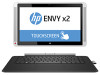
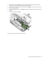
Solid-state drive Description 512-GB, M2, SATA-3, TLC 256-GB, M2, SATA-3, TLC 128-GB, M2, SATA-3, TLC Spare part number 787264-001 787288-001 787287-001 Before removing the solid-state drive, follow these steps: 1. Shut down the computer. If you are unsure whether the computer is off or in Hibernation, turn the computer on, and then shut it down through the operating system. 2. Disconnect all external devices connected to the computer. 3. Disconnect the power from the computer by first unplugging the power cord from the AC outlet and then unplugging the AC adapter from the computer. 4. Remove the back cover (see Back cover on page 22). 5. Disconnect the battery cable from the system board (see Battery on page 25). Remove the solid-state drive: 1. Remove the Phillips PM1.9×3.3 screw (1) that secures the solid-state drive to the display panel assembly. (The solid-state drive tilts up.) Component replacement procedures 31
-
 1
1 -
2
-
3
-
4
-
5
-
6
-
7
-
8
-
9
-
10
-
11
-
12
-
13
-
14
-
15
-
16
-
17
-
18
-
19
-
20
-
21
-
22
-
23
-
24
-
25
-
26
-
27
-
28
-
29
-
30
-
31
-
 32
32 -
 33
33 -
 34
34 -
 35
35 -
 36
36 -
 37
37 -
 38
38 -
 39
39 -
 40
40 -
 41
41 -
 42
42 -
43
-
44
-
45
-
46
-
47
-
48
-
49
-
50
-
51
-
52
-
53
-
54
-
55
-
56
-
57
-
58
-
59
 |
 |