HP ENVY x2 - 13-j012dx HP ENVY x2 (model numbers 13- j000 through 13-j099) Mai - Page 41
Remove the Philllips PM1.9×3.3 screw, Remove the connector board
 |
View all HP ENVY x2 - 13-j012dx manuals
Add to My Manuals
Save this manual to your list of manuals |
Page 41 highlights
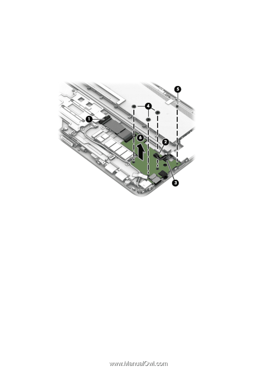
3. Release the ZIF connector (3) to which the volume button board cable is attached, and then disconnect the volume button board cable from the system board. 4. Remove the three Philllips PM1.9×2.5 broad head screws (4) that secure the connector board to the display panel assembly. 5. Remove the Philllips PM1.9×3.3 screw (5) that secures the connector board to the display panel assembly. 6. Remove the connector board (6). Reverse this procedure to install the connector board. Component replacement procedures 35
-
 1
1 -
2
-
3
-
4
-
5
-
6
-
7
-
8
-
9
-
10
-
11
-
12
-
13
-
14
-
15
-
16
-
17
-
18
-
19
-
20
-
21
-
22
-
23
-
24
-
25
-
26
-
27
-
28
-
29
-
30
-
31
-
32
-
33
-
34
-
35
-
 36
36 -
 37
37 -
 38
38 -
 39
39 -
 40
40 -
 41
41 -
 42
42 -
 43
43 -
 44
44 -
 45
45 -
 46
46 -
47
-
48
-
49
-
50
-
51
-
52
-
53
-
54
-
55
-
56
-
57
-
58
-
59
 |
 |
3.
Release the ZIF connector
(3)
to which the volume button board cable is attached, and then
disconnect the volume button board cable from the system board.
4.
Remove the three Philllips PM1.9×2.5 broad head screws
(4)
that secure the connector board to
the display panel assembly.
5.
Remove the Philllips PM1.9×3.3 screw
(5)
that secures the connector board to the display panel
assembly.
6.
Remove the connector board
(6)
.
Reverse this procedure to install the connector board.
Component replacement procedures
35