HP ENVY x2 - 13-j012dx HP ENVY x2 (model numbers 13- j000 through 13-j099) Mai - Page 40
Connector board, Release the ZIF connector
 |
View all HP ENVY x2 - 13-j012dx manuals
Add to My Manuals
Save this manual to your list of manuals |
Page 40 highlights
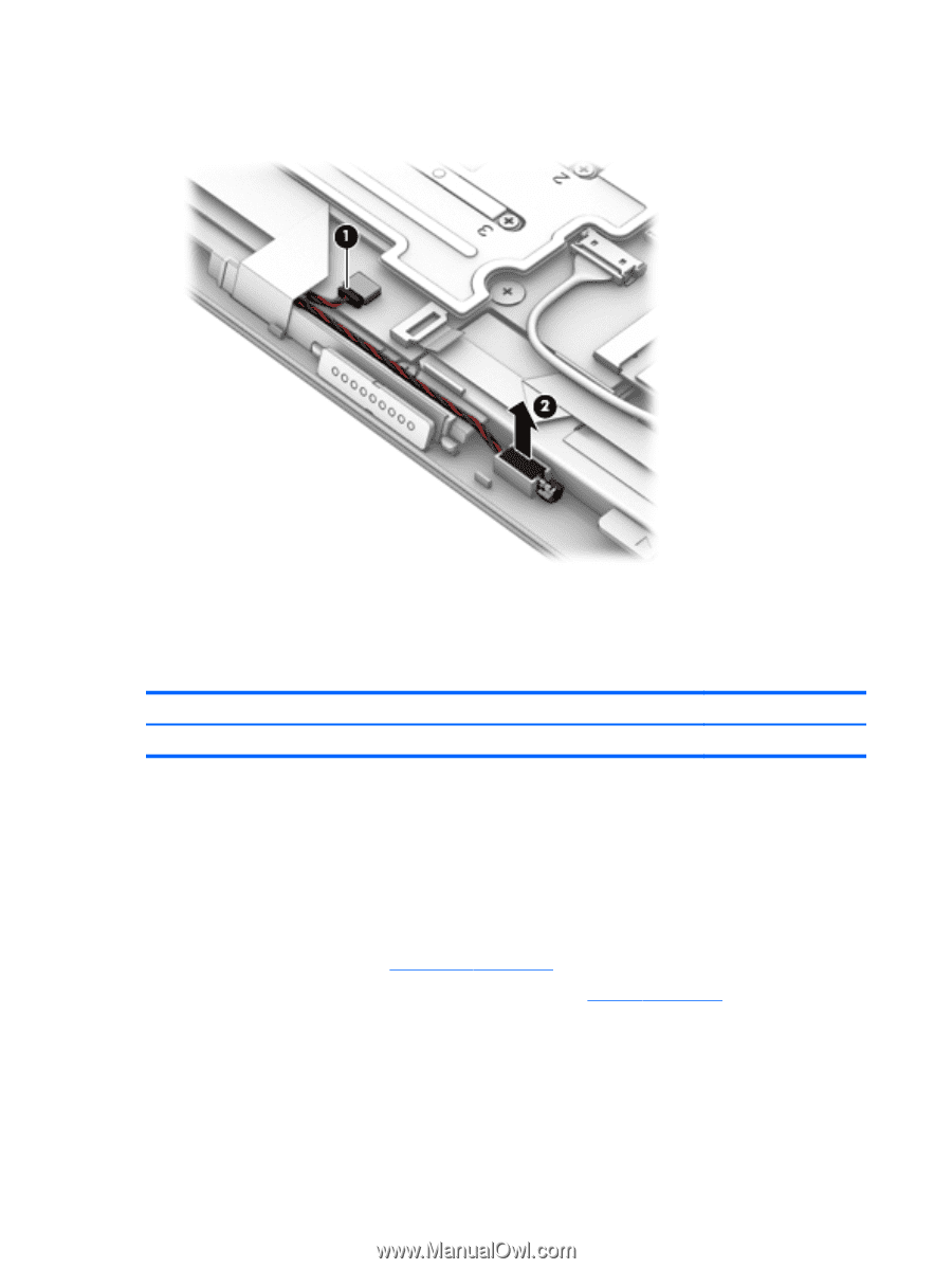
1. Disconnect the vibrator module cable (1) from the system board. 2. Release the vibrator module (2) from the retention molding built into the display panel assembly. 3. Remove the vibrator module. Reverse this procedure to install the vibrator module. Connector board Description Connector board (includes audio jack, USB port, and cable) Spare part number 787267-001 Before removing the connector board, follow these steps: 1. Shut down the computer. If you are unsure whether the computer is off or in Hibernation, turn the computer on, and then shut it down through the operating system. 2. Disconnect all external devices connected to the computer. 3. Disconnect the power from the computer by first unplugging the power cord from the AC outlet and then unplugging the AC adapter from the computer. 4. Remove the back cover (see Back cover on page 22). 5. Disconnect the battery cable from the system board (see Battery on page 25). Remove the connector board: 1. Release the ZIF connector (1) to which the connector board cable is attached, and then disconnect the connector board cable from the system board. 2. Disconnect the speaker cable (2) from the connector board. 34 Chapter 5 Removal and replacement procedures
-
 1
1 -
2
-
3
-
4
-
5
-
6
-
7
-
8
-
9
-
10
-
11
-
12
-
13
-
14
-
15
-
16
-
17
-
18
-
19
-
20
-
21
-
22
-
23
-
24
-
25
-
26
-
27
-
28
-
29
-
30
-
31
-
32
-
33
-
34
-
 35
35 -
 36
36 -
 37
37 -
 38
38 -
 39
39 -
 40
40 -
 41
41 -
 42
42 -
 43
43 -
 44
44 -
 45
45 -
46
-
47
-
48
-
49
-
50
-
51
-
52
-
53
-
54
-
55
-
56
-
57
-
58
-
59
 |
 |