HP Elite 7100 Maintenance & Service Guide: HP Elite 7100 Series Microtower - Page 54
Installing an Optical Drive into the 5.25-inch Drive Bay, on Preparation for Disassembly
 |
View all HP Elite 7100 manuals
Add to My Manuals
Save this manual to your list of manuals |
Page 54 highlights
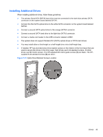
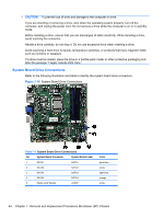
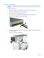
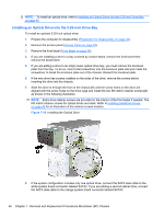
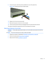
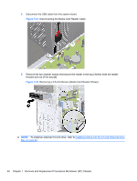
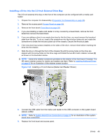
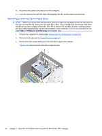
NOTE: To install an optical drive, refer to Installing an Optical Drive into the 5.25-inch Drive Bay on page 46. Installing an Optical Drive into the 5.25-inch Drive Bay To install an optional 5.25-inch optical drive: 1. Prepare the computer for disassembly (Preparation for Disassembly on page 28). 2. Remove the access panel (Access Panel on page 29). 3. Remove the front bezel (Front Bezel on page 30). 4. If you are installing a drive in a bay covered by a bezel blank, remove the front bezel then remove the bezel blank. 5. If you are adding a drive to an empty lower optical drive bay, you must remove the knockout plate from the bay. To do so, insert a flat screwdriver into the knockout plate slot and rotate the screwdriver to break the knockout plate out of the chassis. Discard the knockout plate. 6. If the new drive has screws installed on the sides of the drive, remove the screws before inserting the drive into the chassis. 7. Slide the drive in through the front of the chassis (1) until the screw holes on the drive are aligned with the screw holes on the drive cage and install the two M3 metric retainer screws (2) as shown in the following illustration. NOTE: Extra drive retainer screws are provided on the interior of the front bezel if needed. The M3 metric retainer screws for optical drives are black. Refer to Installing Additional Drives on page 43 for an illustration of the retainer screws location. Figure 7-19 Installing the Optical Drive 8. If the system configuration includes only one optical drive, connect the SATA data cable to the white system board connector labeled SATA2. If you are adding a second optical drive, connect the SATA data cable to the orange system board connector labeled SATA4. 46 Chapter 7 Removal and Replacement Procedures Microtower (MT) Chassis
-
 1
1 -
2
-
3
-
4
-
5
-
6
-
7
-
8
-
9
-
10
-
11
-
12
-
13
-
14
-
15
-
16
-
17
-
18
-
19
-
20
-
21
-
22
-
23
-
24
-
25
-
26
-
27
-
28
-
29
-
30
-
31
-
32
-
33
-
34
-
35
-
36
-
37
-
38
-
39
-
40
-
41
-
42
-
43
-
44
-
45
-
46
-
47
-
48
-
 49
49 -
 50
50 -
 51
51 -
 52
52 -
 53
53 -
 54
54 -
 55
55 -
 56
56 -
 57
57 -
 58
58 -
 59
59 -
60
-
61
-
62
-
63
-
64
-
65
-
66
-
67
-
68
-
69
-
70
-
71
-
72
-
73
-
74
-
75
-
76
-
77
-
78
-
79
-
80
-
81
-
82
-
83
-
84
-
85
-
86
-
87
-
88
-
89
-
90
-
91
-
92
-
93
-
94
-
95
-
96
-
97
-
98
-
99
-
100
-
101
-
102
-
103
-
104
-
105
-
106
-
107
-
108
-
109
-
110
-
111
-
112
-
113
-
114
-
115
-
116
-
117
-
118
-
119
-
120
-
121
-
122
-
123
-
124
-
125
-
126
-
127
 |
 |