HP GbE2c HP GbE2c Layer 2/3 Ethernet Blade Switch for c-Class BladeSystem User - Page 16
Planning the switch configuration - ethernet blade switch firmware
 |
UPC - 808736802215
View all HP GbE2c manuals
Add to My Manuals
Save this manual to your list of manuals |
Page 16 highlights
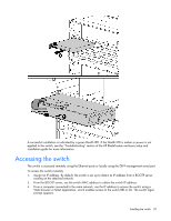
Installing the switch In this section Planning the switch configuration ...16 Installing the switch ...19 Accessing the switch...20 Logging on and configuring the switch...21 Installing SFP transceivers ...21 Supporting software and special considerations 22 Planning the switch configuration NOTE: Only one port number can be used at a time. SFP transceiver ports have priority over the RJ-45 ports. The switch ships with a default configuration in which all downlink and uplink ports are enabled and assigned a default VLAN with a VID equal to 1. This default configuration simplifies the initial setup by allowing use of a single uplink cable (from any external Ethernet connector) to connect the server blade enclosure to the network. By default, the X-connect ports (17 and 18) are disabled. Assess the particular server environment to determine any requirements for other considerations. The switch does not affect or determine NIC numeration and the associated mapping of NIC interfaces to switch ports. The numbering of the NICs on the server (for example, NIC 1, NIC 2, NIC 3) is determined by the server type, the server operating system, and which NICs are enabled on the server. NOTE: Port 19 is reserved for connection to the Onboard Administrator module for switch management. This allows a user to enable the functionality of future firmware upgrade releases. The Onboard Administrator module controls all port enabling. Enabling is based on matching ports between the server and the interconnect bay. Before power up, the Onboard Administrator module verifies that the server NIC option matches the switch bay that is selected and enables all ports for the NICs installed. For detailed port mapping information, see the HP BladeSystem enclosure installation poster or the HP BladeSystem enclosure setup and installation guide on the HP website (http://www.hp.com/go/bladesystem/documentation). Default settings The switch ships with a default configuration in which all downlink and uplink ports are enabled and assigned a default VLAN with a VID equal to 1. This default configuration simplifies the initial setup by allowing use of a single uplink cable (from any external Ethernet connector) to connect the server blade enclosure to the network. By default, the X-connect ports (17 and 18) are disabled. Assess the particular server environment to determine any requirements for other considerations. The switch does not affect or determine NIC numeration and the associated mapping of NIC interfaces to switch ports. The numbering of the NICs on the server (for example, NIC 1, NIC 2, NIC 3) is determined by the server type, the server operating system, and what NICs are enabled on the server. Installing the switch 16
-
 1
1 -
2
-
3
-
4
-
5
-
6
-
7
-
8
-
9
-
10
-
 11
11 -
 12
12 -
 13
13 -
 14
14 -
 15
15 -
 16
16 -
 17
17 -
 18
18 -
 19
19 -
 20
20 -
 21
21 -
22
-
23
-
24
-
25
-
26
-
27
-
28
-
29
-
30
-
31
-
32
-
33
-
34
-
35
-
36
-
37
-
38
-
39
-
40
-
41
-
42
-
43
-
44
-
45
-
46
-
47
-
48
-
49
-
50
-
51
-
52
-
53
-
54
-
55
-
56
-
57
-
58
-
59
-
60
 |
 |
