HP Indigo ws4500 Rewinder Service
HP Indigo ws4500 - Digital Press Manual
 |
View all HP Indigo ws4500 manuals
Add to My Manuals
Save this manual to your list of manuals |
HP Indigo ws4500 manual content summary:
- HP Indigo ws4500 | Rewinder Service - Page 1
Document details Purpose To describe how to service the rewinder Scope HP Indigo WS6000 Digital Press, HP Indigo WS6600 Digital Press, HP Indigo WS6800 Digital Press, HP Indigo WS4500 Digital Press, HP Indigo WS4600 Digital Press. Document number CA393-00580 Revision number Rev 04 Date - HP Indigo ws4500 | Rewinder Service - Page 2
packer arm...54 Disassembling the packer arm adjustable external assembly 55 Installing the new packer arm ...56 Aligning the packer arm...56 Replacing the web guide ...57 Old type of web - HP Indigo ws4500 | Rewinder Service - Page 3
Replacing the old type of web guide ...59 Setup instructions ...60 Stage #1...60 Stage #2...61 Parameter declaration...62 Resetting the web guide ultrasonic sensor (new type 64 and confidentiality notice ...84 Revision History...84 Printing instructions ...84 Confidentiality notice...85 iii - HP Indigo ws4500 | Rewinder Service - Page 4
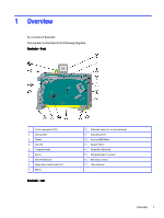
) 9 Wheels Rewinder - rear 10 Ultrasonic Sensor for roll measurement 11 Expanding shaft 12 Structure RHS Beam 13 Pads Ø125mm 14 Packer Arm (Optional) 15 Web guide adjusting sensor 16 Emergency button 17 Tape dispenser Overview 1 - HP Indigo ws4500 | Rewinder Service - Page 5
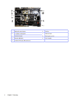
1 Web guide control system 2 Pneumatic control system 3 Connections plate 4 Structure RHS Beam 5 Unidrive CT-Net, and LAN connections 6 Unidrive 7 Motor and gear 8 Dancer glass cylinder 9 Potentiometer 2 Chapter 1 Overview - HP Indigo ws4500 | Rewinder Service - Page 6
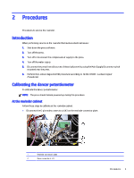
When performing service on the rewinder that involves electrical issues: 1. Shut down the press software. 2. Turn off the press. 3. Turn off or disconnect the compressed air supply to the press. 4. Turn off the water supply. 5. Disconnect the press from all sources of electrical power by using the - HP Indigo ws4500 | Rewinder Service - Page 7
3 Potentiometer cable At the rewinder potentiometer Follow these steps to calibrate at the rewinder potentiometer. 1. Use a 2.0 mm Hex key to loosen the set screw securing the potentiometer coupling to the rotating arm shaft of the dancer. 1 Dancer arm shaft 2 Hex 2.0 mm - HP Indigo ws4500 | Rewinder Service - Page 8
2. Straighten the dancer arm axle shaft so that the shaft and piston shaft are at right angles. 1 Dancer axle shaft 2 Piston shaft 3. While holding the potentiometer coupling with one hand, insert the two cable pins from a DVM, set to measure Ohm values (Resistance), to two pins of the 6-pin - HP Indigo ws4500 | Rewinder Service - Page 9
: When replacing or resetting the PLC memory card, you must calibrate both the dancer and the ultrasonic sensor. Calibrating the dancer Calibration of the dancer. Manually rotate the dancer counter-clockwise until it is at an angle of approximately -40° as shown below. 6 Chapter 2 Procedures - HP Indigo ws4500 | Rewinder Service - Page 10
At the touch screen panel (TSP) Calibration at the touch screen panel. 1. Press the diagnostic icon . Dancer position window opens. 2. Select next window by pressing the next page icon . Then select Technician. 3. Press the button for more than two seconds. The dancer may rotate slightly and - HP Indigo ws4500 | Rewinder Service - Page 11
4. Manually rotate the dancer clockwise until it is at an angle of approximately +40°. At the TSP Calibration at the TSP. Press the button the ultrasonic sensor Ultrasonic sensor calibration. 1. Select Roll Diameter window by pressing the next page icon . 2. Measure the diameter of the empty core - HP Indigo ws4500 | Rewinder Service - Page 12
a value that is 10x the actual value. If the diameter is 74mm, enter 740. 3. Mount the core on the rewind shaft. 1 Ultrasonic sensor 2 Rewind shaft 4. Press the button next to the Small diameter Setup field for more than two seconds and make sure that the Roll diameter value at the lower - HP Indigo ws4500 | Rewinder Service - Page 13
roll on the unwind shaft. 1 Unwind shaft 7. Press the button next to the Big diameter Setup field for Replacing the dancer glass cylinder Replacement of the dancer glass cylinder. 1. Shut down the press and release the air pressure from the UW air gun. 2. Disconnect the air supply tube - HP Indigo ws4500 | Rewinder Service - Page 14
from both sides of the cylinder and remove the cylinder. 4. Install the new glass cylinder using the original two screws. 5. Connect the air supply tube to the cylinder. 6. Turn the press on. Preparation for replacing an idler Preparation to replace an idler. Removing the splicing table Removal - HP Indigo ws4500 | Rewinder Service - Page 15
may be necessary for the following operations. 3. Carefully loosen the six sets of Hex M6 screws securing the splicing table arms to the rewinder wall. 4. Support the splicing table at both ends to prevent the table dropping when the screws are removed. 5. Remove all screws and washers securing the - HP Indigo ws4500 | Rewinder Service - Page 16
an idler at the rewinder. 1. Shut down the press. 2. Remove the three hex M6 screws and screw M6 screws 4 Screw bushing 6 Idler shaft 4. Install the new idler and bushing to the rewinder using the original screws and screw bushings. Do not tighten the securing screws. 5. Check the leveling on - HP Indigo ws4500 | Rewinder Service - Page 17
a. Loosen the idler roller securing screws. 1, 2 Securing screws 3 Bushings b. Align the roller's bushings to the roller's shaft using the level. c. Tighten the idler roller securing screws. 14 Chapter 2 Procedures - HP Indigo ws4500 | Rewinder Service - Page 18
d. If the rewinder splicing table is removed, use the alignment jig as shown below. Otherwise, place the alignment jig between the relevant rewinder and the press rollers to align the new rewinder roller as shown below. At the rewinder 15 - HP Indigo ws4500 | Rewinder Service - Page 19
press and rewinder. Reinstalling the splicing table It explains how to reinstall the splicing table. At the rear of the rewinder Reinstall the splicing table at the rear of the rewinder. 1. Support the air tubes to the splicing table using tie wraps. 8. Restart the press. 16 Chapter 2 Procedures - HP Indigo ws4500 | Rewinder Service - Page 20
. 3. Turn off or disconnect the compressed air supply to the press. 4. Turn off the water supply. 5. Disconnect the press from all sources of electrical power by using the Main Supply Disconnect switch mounted near the press. 6. Perform the Lockout-Tagout (LOTO) procedure (according to CA493-00080 - HP Indigo ws4500 | Rewinder Service - Page 21
3. Use a hex M8 key to loosen the four gear securing screws securing the motor gear plate to the moving shelf assembly. 1 Rewinder drive 2 Gear securing screws (x4) 3 Motor 4 Belt tension adjustment screw 5 Motor drive 6 Motor gear plate 7 Gear drive belt 18 Chapter 2 Procedures - HP Indigo ws4500 | Rewinder Service - Page 22
4. Loosen the belt tension adjustment screw completely to allow free movement of the motor gear plate. 1 Belt tension adjustment screw 2 Belt tension adjustment bracket 3 Motor gear plate 4 Belt tension adjustment screw fully released 5. Move the motor gear to slacken the tension in the - HP Indigo ws4500 | Rewinder Service - Page 23
. Reconnect the orange power cable and green encoder connectors to the motor. 16. Reinstall the motor gear guard using the original two securing screws. 17. Start the press. Make sure that the moving shelf assembly and rotating rewind roller operates correctly. Replacing the servo motor Replacement - HP Indigo ws4500 | Rewinder Service - Page 24
screws and washers securing the motor to the platform that its mounted on. Leave only the screw that's located on rear-right side (see right image below), to hold the motor in place, for now. Replacing the servo motor 21 - HP Indigo ws4500 | Rewinder Service - Page 25
3. Unscrew the tensor screw. 4. Slide the motor towards the right side of the shelf/platform. 22 Chapter 2 Procedures - HP Indigo ws4500 | Rewinder Service - Page 26
5. Loosen and release the gear belt from the gear wheel of the motor. 6. Dismount the motor from its platform, and carefully place it on a pallet (requires 2 people). Replacing the servo motor 23 - HP Indigo ws4500 | Rewinder Service - Page 27
7. Remove the new servo motor (CA345-56661) from its box, and carefully mount it on the motor platform. 8. Insert the hex screw in the rear right corner, to secure the motor to its platform. Do not tighten it all the way, to enable shifting the motor to the left. 9. Slide the motor to the left. 24 - HP Indigo ws4500 | Rewinder Service - Page 28
10. Place the gear belt on the motor's gear wheel. 11. Insert the tension screw, but do not tighten it yet. 12. Insert the remaining 3 hex screws and washers that attach the motor to its platform, and tighten them. Replacing the servo motor 25 - HP Indigo ws4500 | Rewinder Service - Page 29
13. Tighten the tensor screw, until the tension in the gear belt is in the range of: 999Nm / 195Hz (min) to 1100Nm / 204Hz (max). Refer to document CA345-56346. 14. Disconnect the green encoder cable from its connector, and dispose of it. 15. Connect the new green encoder cable ("Rewinder Feedback - HP Indigo ws4500 | Rewinder Service - Page 30
that appears in page 40 of document CA364-00320. 18. Reconnect the orange power cable and green encoder connectors to the motor. 19. Start the press and the rewinder. 20. Make sure that the moving shelf assembly and rotating rewind roller operates correctly. Replacing the servo motor 27 - HP Indigo ws4500 | Rewinder Service - Page 31
inside the controller connector, between slots 22 and 24. Installing a new packer arm To install the packer arm assembly: ● Shut down the press as described in "Introduction on page 3". ● For easy access to the rewinder cabinet, remove the cabinet doors. Installing the internal packer arm assembly - HP Indigo ws4500 | Rewinder Service - Page 32
2. At the rear of the rewinder, position the internal packer arm assemblyThe internal packer arm assembly is heavy, and should be handled by two people. 3. From the rear of the rewinder, remove and discard the circular plate. Installing the internal packer arm assembly 29 - HP Indigo ws4500 | Rewinder Service - Page 33
4. From the rear of the rewinder, push the internal packer arm assembly through the hole. 30 Chapter 2 Procedures - HP Indigo ws4500 | Rewinder Service - Page 34
5. From the front of the rewinder, pull the internal packer arm assembly through the hole. Installing the internal packer arm assembly 31 - HP Indigo ws4500 | Rewinder Service - Page 35
6. From the front of the rewinder, install the two Hex M6 screws to secure the internal packer arm assembly wall bracket. 7. From the rear of the rewinder, move the connecting plate towards the moving shelf assemblyMake sure that the holes in the connecting plate align with the holes in the moving - HP Indigo ws4500 | Rewinder Service - Page 36
8. Install 4 hex M6 screws, washers, and spring washers to secure the vertical plate to the side of the internal packer arm assembly. Do not tighten the screws. Installing the internal packer arm assembly 33 - HP Indigo ws4500 | Rewinder Service - Page 37
9. Install and tighten the four connecting plate screws. 10. Tighten the four vertical plate screws. 11. From the bottom of the cylinder plate, tighten the four cylinder plate screws. 34 Chapter 2 Procedures - HP Indigo ws4500 | Rewinder Service - Page 38
12. Install the electro-pneumatic regulator in the base using 4 hex M6 screws. 13. Connect the electro-pneumatic regulator plug. Installing the internal packer arm assembly 35 - HP Indigo ws4500 | Rewinder Service - Page 39
14. Install the base mount assembly. 15. Connect the base mount plug. 36 Chapter 2 Procedures - HP Indigo ws4500 | Rewinder Service - Page 40
16. Install the tie-wrap mount. Preparing the external packer arm assembly Preparation to install the external packer arm assembly 1. Shorten the external packer arm tube by cutting it after the white tie-wrap mount. Preparing the external packer arm assembly 37 - HP Indigo ws4500 | Rewinder Service - Page 41
a. Before cutting tube b. After cutting tube 2. Install the elbow fitting in the shortened tube. 38 Chapter 2 Procedures - HP Indigo ws4500 | Rewinder Service - Page 42
3. Install one tie-wrap around the elbow fittingInstall another tie-wrap around the tube. 1 Tie-wrap around elbow fitting 2 Tie-wrap around tube Installing the external packer arm assembly To install the external packer arm assembly: 1. From the front of the rewinder, loosen the three external - HP Indigo ws4500 | Rewinder Service - Page 43
arm assembly 3. To level the external packer arm assembly: a. Manually raise the lower packer arm cylinder until it touches the rewinder expanding shaft cylinder. b. Use a level to ensure that the lower packer arm cylinder is leveled. c. Use a filler gauge to ensure that the two cylinders are - HP Indigo ws4500 | Rewinder Service - Page 44
d. To align the packer arm idler cylinder, use the external packer arm bolts as push and pull mechanisms. Preparing the tubes Preparation to install the tubes. 1. Cut the 6 mm black tube (P/N 0890-2334) - HP Indigo ws4500 | Rewinder Service - Page 45
● Connect the main tube as shown. Installing the clamp tube Installation of the clamp tube. 42 Chapter 2 Procedures - HP Indigo ws4500 | Rewinder Service - Page 46
1. From the rear of the rewinder, connect the clamp tube to the front-right port (behind the pressure gauge) of the manifold. Installing the clamp tube 43 - HP Indigo ws4500 | Rewinder Service - Page 47
2. Install the clamp tube in the clips, as follows: Clamp tube in clips Clamp tube in clips 44 Chapter 2 Procedures - HP Indigo ws4500 | Rewinder Service - Page 48
Clamp tube in clips Installing the clamp tube 45 - HP Indigo ws4500 | Rewinder Service - Page 49
3. Thread the clamp tube through the hole. Clamp tube - rear of rewinder 4. From the front of the rewinder, pull the clamp tube through the holeConnect the clamp tube to the fitting. Clamp tube - front of rewinder 46 Chapter 2 Procedures - HP Indigo ws4500 | Rewinder Service - Page 50
1 Clamp tube Installing the short tube Installation of the short tube. 2 Fitting Installing the short tube 47 - HP Indigo ws4500 | Rewinder Service - Page 51
1. Connect the short tube to the right port of the electro-pneumatic regulator. 48 Chapter 2 Procedures - HP Indigo ws4500 | Rewinder Service - Page 52
2. Connect the short tube to the right port of the base mount assembly. Installing the engagement and disengagement tubes Installation of the engagement and disengagement tubes. 1. Connect the black engagement tube to the bottom-left port of the base mount assembly. Installing the engagement and - HP Indigo ws4500 | Rewinder Service - Page 53
2. Connect the clear disengagement tube to the top-left port of the base mount assembly. 50 Chapter 2 Procedures - HP Indigo ws4500 | Rewinder Service - Page 54
3. Insert the engagement and disengagement tubes into the clips, as follows: 4. Connect the clear disengagement tube to the top flow controller. Installing the engagement and disengagement tubes 51 - HP Indigo ws4500 | Rewinder Service - Page 55
5. Connect the black engagement tube to the bottom flow controller. NOTE: The valves on the piston are shipped in the closed position so that the piston will not open during shipping. Open the valves during the installation of the kit by turning the top and bottom knobs 2 turns counterclockwise. - HP Indigo ws4500 | Rewinder Service - Page 56
6. Set the air pressure to 0.2 bars. Installing the engagement and disengagement tubes 53 - HP Indigo ws4500 | Rewinder Service - Page 57
It explains the replacement of the packer arm. Disassembling the packer arm Follow these steps to disassemble the packer arm. 1. Shut down the press as described in "Introduction on page 3" . 2. Remove the 3 hex M8 screws securing the adjustable bushing to the packer arm fixed inner assembly. Remove - HP Indigo ws4500 | Rewinder Service - Page 58
1 Rail base assembly 2 Main shaft roller 3 Cylinder arm 4 Packer arm pressure piston 5 Packer arm adjustable external assembly 6 Hex M8 screws Disassembling the packer arm adjustable external assembly Follow these steps to disassemble the packer arm adjustable external assembly. The idler is - HP Indigo ws4500 | Rewinder Service - Page 59
assembly walls, remove the four screws securing the clamp. Remove clamp and discard. Save the securing screws. b. Mount the new clamp and secure using the original screws. Installing the new packer arm Installation of the new packer arm. After the packer arm is disassembled, install the new packer - HP Indigo ws4500 | Rewinder Service - Page 60
alignment procedure. 4. Check that the lower pack arm roller is parallel relative to the expanding shaft using a level positioned as shown below. Replacing the web guide Replacement of the web guide. 1. Shut off the power to the rewinder. 2. Remove the substrate roll from the drive shaft. Replacing - HP Indigo ws4500 | Rewinder Service - Page 61
3. On the back side of the rewinder, remove the cover of the motor and gear. 4. Disconnect the 2 electrical connectors to the web guide. 5. Remove the hex screw holding the web guide to the base plate. 58 Chapter 2 Procedures - HP Indigo ws4500 | Rewinder Service - Page 62
the rear side of the rewinder, pull the web guide out of the press. 8. To return the web guide, perform the above steps in reverse order. Old type of web guide It explains how to replace the old type of web guide. Replacing the old type of web guide Replacement of the old type of web - HP Indigo ws4500 | Rewinder Service - Page 63
3 key pads (located on the top left side of the board) as described below in Setup instructions on page 60 Setup instructions It explains how to setup web guide by using the 3 key pads. 1. Hold the setup button & use the up/down arrows in order to reach the required parameter. 2. Once you reach the - HP Indigo ws4500 | Rewinder Service - Page 64
2. Go to parameter 3 (service functions) & set the value to 10. 3. Go to parameter 4. 4. Now follow the paper) in manual mode and automatic mode: 11. Go to parameter 24 (motion direction) & change the value (0 to 1 or 1 to 0). Stage #2 Stage #2 setup instructions of web guide. 1. After this - HP Indigo ws4500 | Rewinder Service - Page 65
(configuration of input x4.7) & set the value d. = Save parameters. Go to parameter 3 & set the value to 1 (service function Reset) e. Go to parameter 4. f. Press on the on/off web guide button on the TSP & check that the ultrasonic edge sensor follows the on/off command. Parameter declaration - HP Indigo ws4500 | Rewinder Service - Page 66
. These position range limits must not be used as safeguards for persons or appliances. For means that the positioning roller is parallel to the guide roller. If the guider is in "center position input X20.2 .8.6. >usage input X 3.2 The digital inputs (see wiring diagram) may be assigned functions. - HP Indigo ws4500 | Rewinder Service - Page 67
sensor does not respond, reset the sensor as shown below. 1. Locate the web guide sensor on the rewinder 2. Push button A 5 times to reset the sensor. Replacing the drive shaft and the inflatable balloons (for the new type shaft p/n CU153- - HP Indigo ws4500 | Rewinder Service - Page 68
1. Loosen the 4 screws holding the drive shaft gear to the base plate. 2. Loosen the belt-tightening screw underneath the gear. 3. Disconnect the air tube from the fitting on the drive shaft. Replacing the drive shaft and the inflatable balloons (for the new type shaft p/n CU153-02574) 65 - HP Indigo ws4500 | Rewinder Service - Page 69
4. Remove the 2 set screws from the inner ring of the lower drive belt pulley. 5. Insert one of the set screws into the 3rd screw hole and tighten the screw. 6. As you tighten the screw, the inner ring will be pushed out of the pulley. Remove the ring. 66 Chapter 2 Procedures - HP Indigo ws4500 | Rewinder Service - Page 70
7. Remove the drive belt from the lower pulley and then from the upper pulley. 8. Use a 14 mm open wrench to remove the air inlet from the drive roller shaft. 9. Remove the 2 set screws from the ring holding the drive roller - HP Indigo ws4500 | Rewinder Service - Page 71
10. From the front side of the rewinder, pull out the drive roller shaft. 11. Place the shaft on a flat surface. 12. Loosen the set screw in the cap ring of the inflatable balloon housing and remove the ring. 13. Loosen the 3 hex screws at the other end of the inflatable balloon housing and remove - HP Indigo ws4500 | Rewinder Service - Page 72
14. Loosen the 2 screws in the bracket at each end of the inflatable piston. There are 3 pistons. Remove the brackets on each of the 3 pistons. 15. Slide the pistons out of the housing. 16. Slide the inflatable balloon out of the housing. Be careful not to lose the rubber O-ring which seals between - HP Indigo ws4500 | Rewinder Service - Page 73
only 1 set of ridges. Install the shim with one set of ridges on the end of the balloon with the air inlet. Install the shim with 2 sets of ridges on the other end of the balloon. 19. Install the shims so that the ridges are facing down and touching the ridges on the balloon. 20. Return the end - HP Indigo ws4500 | Rewinder Service - Page 74
21. Put grease on the drive shaft and insert the shaft carefully into the rewinder. 22. Tighten the set screws holding the drive shaft on the rear side of the rewinder. 23. Insert the key into the drive shaft and return the inner ring and pulley. Replacing the drive shaft and the inflatable balloons - HP Indigo ws4500 | Rewinder Service - Page 75
24. Install the drive belt, making sure that it is straight. Insert the screws into the pulley inner ring. 25. Reinsert the air inlet and the air hose. 26. Apply tension to the drive belt by tightening the tension screw. 72 Chapter 2 Procedures - HP Indigo ws4500 | Rewinder Service - Page 76
27. Reinstall the gear and motor cover. Replacing the inflatable balloon for older shafts (p/n CU153-02583) Replacement of the inflatable balloon for older shafts. 1. Remove the end cap from the shaft by loosening the hex screws. Replacing the inflatable balloon for older shafts (p/n CU153-02583) 73 - HP Indigo ws4500 | Rewinder Service - Page 77
2. Remove the outer pressure platesThere are 3 plates and 3 screws on each plate. 74 Chapter 2 Procedures - HP Indigo ws4500 | Rewinder Service - Page 78
3. There are 6 pistons under each pressure plate. Replacing the inflatable balloon for older shafts (p/n CU153-02583) 75 - HP Indigo ws4500 | Rewinder Service - Page 79
4. Insert hex screws into the 1st and 3rd piston on each side. There are pistons on six sides. 5. 2 persons should pull the screws out while a 3rd person pulls out the inner balloon. When to pull out the balloon, pull on the inner screw. 76 Chapter 2 Procedures - HP Indigo ws4500 | Rewinder Service - Page 80
6. When the inner end of the balloon has passed the inner pistons, pull out the screws on the outer pistons and pull the balloon out of the shaft. 7. Insert the new balloon. Pull the outer screws when starting to insert the new balloon and then pull the inner screws to complete the insertion of the - HP Indigo ws4500 | Rewinder Service - Page 81
the rewinder tension values (low, medium and high) in the table above, do the following: a. In the press UI Substrate Properties window, set the rewinder tension parameter to the value in the table. b. Using the green system web feed button on the rewinder, run the web for a few meters. c. Read the - HP Indigo ws4500 | Rewinder Service - Page 82
screen. 6. Press and hold the right button until UNL is displayed. 7. Press the middle button. Loc is displayed. Theory of operation The rewinder collects and winds the substrate as it leaves the printing engine ( unit includes one interlock at the top cover Dancer Web Guide Theory of operation 79 - HP Indigo ws4500 | Rewinder Service - Page 83
Parameters ● Web range 12 to 500 micron ● Product maximum roll diameter: 700 mm ● Product maximum roll diameter with Packer Arm: 500 mm ● Dancer buffer length 370 mm ● Web tension range 0.5 to 12 kg ● Packer Arm force pressure 0.5 to 9kg ● Substrate roll maximum weight: 150 kg Appendix 1- Grease - HP Indigo ws4500 | Rewinder Service - Page 84
the ramp (height, length) and choose a starting line for all sample runs. 3. Measure the dimensions of the rolls (diameter). 4. Prepare the rolls - manually unwind to predetermined thickness (1.1mm, 0.6mm and 0.3mm). 5. Unwind approximately 0.5m of the substrate and place the roll on top of the ramp - HP Indigo ws4500 | Rewinder Service - Page 85
Figure 2-2 test scheme Figure 2-3 ramp placement Figure 2-4 test run and measurement 82 Chapter 2 Procedures - HP Indigo ws4500 | Rewinder Service - Page 86
What to do if the blocking is too high Follow the steps if the blocking is too high. 1. Check the primer condition. Old and contaminated primer can increase the blocking. 2. Make sure that the corona power is not too high, but sufficient for the application. 3. Make sure that the priming level is - HP Indigo ws4500 | Rewinder Service - Page 87
-00580 Rev 03 CA393-00580 Rev 04 Description Initial document Added to scope HP Indigo WS6600, WS6800 and WS4600 Digital Presses Added inflatable shaft replacement and additional services Added section on resetting web guide ultrasonic sensor Added chapter: Replacing the motor and/or motor gear - HP Indigo ws4500 | Rewinder Service - Page 88
valuable trade secrets and confidential information of HP. Nothing herein may be copied, reproduced HP. The copyright notice, which appears in this document, is purely precautionary and shall not be deemed to constitute publication or intent to publish, in whole or in part. © Copyright 2021 HP Indigo
-
 1
1 -
 2
2 -
 3
3 -
 4
4 -
 5
5 -
 6
6 -
 7
7 -
8
-
9
-
10
-
11
-
12
-
13
-
14
-
15
-
16
-
17
-
18
-
19
-
20
-
21
-
22
-
23
-
24
-
25
-
26
-
27
-
28
-
29
-
30
-
31
-
32
-
33
-
34
-
35
-
36
-
37
-
38
-
39
-
40
-
41
-
42
-
43
-
44
-
45
-
46
-
47
-
48
-
49
-
50
-
51
-
52
-
53
-
54
-
55
-
56
-
57
-
58
-
59
-
60
-
61
-
62
-
63
-
64
-
65
-
66
-
67
-
68
-
69
-
70
-
71
-
72
-
73
-
74
-
75
-
76
-
77
-
78
-
79
-
80
-
81
-
82
-
83
-
84
-
85
-
86
-
87
-
88
 |
 |

Rewinder Service
Document details
Purpose
To describe how to service the rewinder
Scope
HP Indigo WS6000 Digital Press, HP Indigo WS6600 Digital Press, HP Indigo WS6800 Digital Press, HP
Indigo WS4500 Digital Press, HP Indigo WS4600 Digital Press.
Document number
CA393-00580
Revision number
Rev 04
Date
16 November 2021
Security level
HP Confidential
The information contained in this document is accurate at the date of release.
Check CE Suitcase for the most recent version of this document.
i