HP J4899B User Manual - Page 21
Installation Location, Installing the Switch 2650, Fiber Optic Cables, Port Type, Cable Type
 |
View all HP J4899B manuals
Add to My Manuals
Save this manual to your list of manuals |
Page 21 highlights
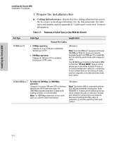
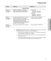
Installing the Switch 2650 Installing the Switch 2650 Installation Procedures Port Type Gigabit-SX (on Gigabit-SX-LC mini-GBIC) Gigabit-LX (on Gigabit-LX-LC mini-GBIC) Gigabit-LH (on Gigabit-LH-LC mini-GBIC) Cable Type Length Limits Fiber Optic Cables 62.5/125 µm or 50/125 µm core/cladding diameter, graded-index, multimode fiber-optic cables that are fitted with LC connectors • 62.5 µm cable: - 160 MHz*km = 220 meters - 200 MHz*km = 275 meters • 50 µm cable: - 400 MHz*km = 500 meters - 500 MHz*km = 550 meters Single-mode cables fitted with LC connectors. 62.5/125 µm or 50/125 µm core/cladding diameter, graded-index, multimode fiber-optic cables may also be used, but a mode conditioning patch cord may be needed - see "Mode Conditioning Patch Cord for Gigabit-LX" on page B-3 for more information. • single-mode cable = 5 kilometers • multimode cable = 550 meters Single-mode cables fitted with LC connectors. • single-mode cable = 70 kilometers ■ Installation Location - Before installing the switch, plan its location and orientation relative to other devices and equipment: • In the front of the switch, leave at least 7.6 cm (3 inches) of space for the twisted-pair and fiber-optic cabling. • In the back of the switch, leave at least 3.8 cm (1 1/2 inches) of space for the power cord. • On the sides of the switch, leave at least 7.6 cm (3 inches) for cooling, except if the switch is installed in an open EIA/TIA rack. 2-5
-
 1
1 -
2
-
3
-
4
-
5
-
6
-
7
-
8
-
9
-
10
-
11
-
12
-
13
-
14
-
15
-
 16
16 -
 17
17 -
 18
18 -
 19
19 -
 20
20 -
 21
21 -
 22
22 -
 23
23 -
 24
24 -
 25
25 -
 26
26 -
27
-
28
-
29
-
30
-
31
-
32
-
33
-
34
-
35
-
36
-
37
-
38
-
39
-
40
-
41
-
42
-
43
-
44
-
45
-
46
-
47
-
48
-
49
-
50
-
51
-
52
-
53
-
54
-
55
-
56
-
57
-
58
-
59
-
60
-
61
-
62
-
63
-
64
-
65
-
66
-
67
-
68
-
69
-
70
-
71
-
72
-
73
-
74
-
75
-
76
-
77
-
78
-
79
-
80
-
81
-
82
-
83
-
84
-
85
-
86
 |
 |
