HP J4899B User Manual - Page 27
Steps 2
 |
View all HP J4899B manuals
Add to My Manuals
Save this manual to your list of manuals |
Page 27 highlights
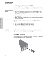
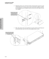
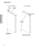
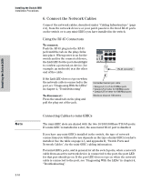
Installing the Switch 2650 Installation Procedures 1. Use a #1 Phillips (cross-head) screwdriver and attach the mounting brackets to the switch with the included 8-mm M4 screws. Installing the Switch 2650 8 mm M4 screws Note Note Note that the mounting brackets have multiple mounting holes and can be rotated allowing for a wide variety of mounting options. These include mounting the switch so that its front face is flush with the face of the rack, or mounting it in a more balanced position as shown in the illustration. Steps 2, 3, and 4 on the next page describe a convenient method of mounting the switch in a rack by placing it on two screws that you first install in the rack. You may, instead, just hold the switch with attached brackets up to the rack and move it vertically until rack holes line up with the bracket holes and notches, then insert and tighten the four screws holding the brackets to the rack. 2-11
-
 1
1 -
2
-
3
-
4
-
5
-
6
-
7
-
8
-
9
-
10
-
11
-
12
-
13
-
14
-
15
-
16
-
17
-
18
-
19
-
20
-
21
-
 22
22 -
 23
23 -
 24
24 -
 25
25 -
 26
26 -
 27
27 -
 28
28 -
 29
29 -
 30
30 -
 31
31 -
 32
32 -
33
-
34
-
35
-
36
-
37
-
38
-
39
-
40
-
41
-
42
-
43
-
44
-
45
-
46
-
47
-
48
-
49
-
50
-
51
-
52
-
53
-
54
-
55
-
56
-
57
-
58
-
59
-
60
-
61
-
62
-
63
-
64
-
65
-
66
-
67
-
68
-
69
-
70
-
71
-
72
-
73
-
74
-
75
-
76
-
77
-
78
-
79
-
80
-
81
-
82
-
83
-
84
-
85
-
86
 |
 |
