HP J4899B User Manual - Page 28
Place the switch in the rack and lower it so the notches in the bottom
 |
View all HP J4899B manuals
Add to My Manuals
Save this manual to your list of manuals |
Page 28 highlights
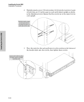
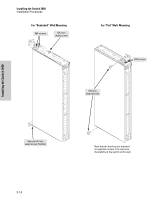
Installing the Switch 2650 Installing the Switch 2650 Installation Procedures 2. Partially install a screw (5/8-inch number 12-24) into the top hole of a pair of holes that are 0.5 inches apart in each rack/cabinet upright as shown in the illustration below. Ensure that the screws are at the same level in each upright. Partially install a screw into the top hole of a close (0.5-inch) pair on both sides of the rack 3. Place the switch in the rack and lower it so the notches in the bottom of the bracket slide onto the screws, then tighten these screws. Lower switch with mounting brackets onto the partially installed screw 2-12
-
 1
1 -
2
-
3
-
4
-
5
-
6
-
7
-
8
-
9
-
10
-
11
-
12
-
13
-
14
-
15
-
16
-
17
-
18
-
19
-
20
-
21
-
22
-
 23
23 -
 24
24 -
 25
25 -
 26
26 -
 27
27 -
 28
28 -
 29
29 -
 30
30 -
 31
31 -
 32
32 -
 33
33 -
34
-
35
-
36
-
37
-
38
-
39
-
40
-
41
-
42
-
43
-
44
-
45
-
46
-
47
-
48
-
49
-
50
-
51
-
52
-
53
-
54
-
55
-
56
-
57
-
58
-
59
-
60
-
61
-
62
-
63
-
64
-
65
-
66
-
67
-
68
-
69
-
70
-
71
-
72
-
73
-
74
-
75
-
76
-
77
-
78
-
79
-
80
-
81
-
82
-
83
-
84
-
85
-
86
 |
 |

2-12
Installing the Switch 2650
Installation Procedures
Installing the Switch 2650
2.
Partially install a screw (5/8-inch number 12-24) into the top hole of a pair
of holes that are 0.5 inches apart in each rack/cabinet upright as shown
in the illustration below. Ensure that the screws are at the same level in
each upright.
3.
Place the switch in the rack and lower it so the notches in the bottom of
the bracket slide onto the screws, then tighten these screws.
Partially install a screw
into the top hole of a
close (0.5-inch) pair on
both sides of the rack
Lower switch with mounting
brackets onto the partially
installed screw