HP LC2000r HP Netserver LC 2000 Installation Guide - Page 23
Power Supply Module Indicator
 |
View all HP LC2000r manuals
Add to My Manuals
Save this manual to your list of manuals |
Page 23 highlights
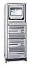
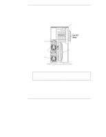
Chapter 2 Controls, Ports and Indicators Power Supply Module Indicator Each HP NetServer power supply module has an indicator as shown in Figure 2-5, and each power supply has its own power cord connection. The HP NetServer comes with one power supply module standard, and a second power supply module for redundancy is optional. Power Indicator Release Latch Handle Strainrelief Figure 2-5. Power Supply LED NOTE The release latch, which is spring loaded, must be up to insert the power cord. The power supply can not be removed from the chassis with the power cord connected to the AC In connector. The power cord must be removed before pushing down on the release latch to free the power supply from the chassis. Table 2-5. Power Supply LED Indicator Descriptions Green LED Power Supply and NetServer Status Steady Green Off This indicates the HP NetServer is powered up and operating normally, or is in an ACPI suspend state. This indicates the NetServer is powered off, the AC line cord is unplugged, or the power supply has failed, which may include a fan failure (turning too slowly). If a fan fails in one of two supplies, the defective supply will continue to operate until it reaches the thermal shutdown limit. The second power supply (redundant power supply) will continue to operate providing the necessary power. Refer to Chapter 12, "Troubleshooting." 15
-
 1
1 -
2
-
3
-
4
-
5
-
6
-
7
-
8
-
9
-
10
-
11
-
12
-
13
-
14
-
15
-
16
-
17
-
 18
18 -
 19
19 -
 20
20 -
 21
21 -
 22
22 -
 23
23 -
 24
24 -
 25
25 -
 26
26 -
 27
27 -
 28
28 -
29
-
30
-
31
-
32
-
33
-
34
-
35
-
36
-
37
-
38
-
39
-
40
-
41
-
42
-
43
-
44
-
45
-
46
-
47
-
48
-
49
-
50
-
51
-
52
-
53
-
54
-
55
-
56
-
57
-
58
-
59
-
60
-
61
-
62
-
63
-
64
-
65
-
66
-
67
-
68
-
69
-
70
-
71
-
72
-
73
-
74
-
75
-
76
-
77
-
78
-
79
-
80
-
81
-
82
-
83
-
84
-
85
-
86
-
87
-
88
-
89
-
90
-
91
-
92
-
93
-
94
-
95
-
96
-
97
-
98
-
99
-
100
-
101
-
102
-
103
-
104
-
105
-
106
-
107
-
108
-
109
-
110
-
111
-
112
-
113
-
114
-
115
-
116
-
117
-
118
-
119
-
120
-
121
-
122
-
123
-
124
-
125
-
126
-
127
-
128
-
129
-
130
-
131
-
132
-
133
-
134
-
135
-
136
-
137
-
138
-
139
-
140
-
141
-
142
-
143
-
144
-
145
-
146
-
147
-
148
-
149
-
150
-
151
-
152
-
153
-
154
-
155
-
156
-
157
-
158
-
159
-
160
-
161
-
162
-
163
-
164
-
165
-
166
-
167
-
168
-
169
-
170
-
171
-
172
-
173
-
174
-
175
-
176
-
177
-
178
-
179
-
180
-
181
-
182
-
183
-
184
-
185
-
186
-
187
-
188
-
189
-
190
-
191
-
192
-
193
-
194
 |
 |
