HP LH4r HP Netserver LH 3/LH 3r to LH 4/LH 4r - Page 21
VRM Name on Baseboard, Proc 1, Proc 2, Proc 3, Proc 4
 |
View all HP LH4r manuals
Add to My Manuals
Save this manual to your list of manuals |
Page 21 highlights
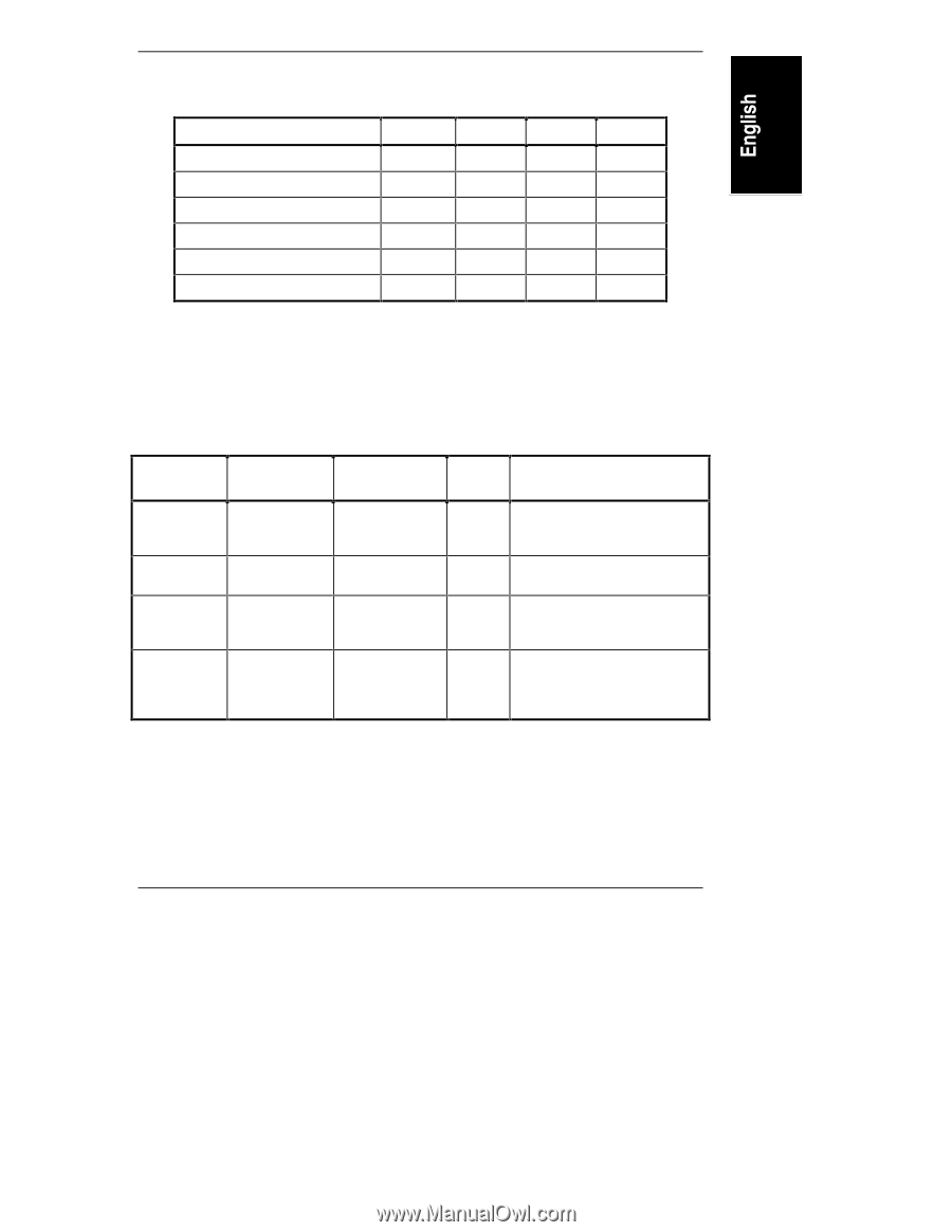
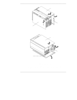
Chapter 3 Installing LH 4 Components Table 3-1. Processor Module and VRM Relationship VRM Name on Baseboard VRM 1/2 VRM 3/4 VRM 1 VRM 2 VRM 3 VRM 4 Proc 1 x x x Proc 2 x x x x Proc 3 x x x x x Proc 4 x x x x x x Note: x = VRM installed Table 3-2 shows the installation requirements for one through four processors: what processor slots to use, how many VRMs are required, and what VRM slots to use. Table 3-2. CPU Baseboard Configurations for 1 Through 4 Processors Processors Processors In: 1 processor Processor 1 2 processors 3 processors 4 processors Processor 1, Processor 2 Processor 1, Processor 2, Processor 3 Processor 1, Processor 2, Processor 3, Processor 4 Terminators In: Processor 2, Processor 3, Processor 4 Processor 3, Processor 4 Processor 4 None VRMs VRMs In: 3 VRMs VRM 1, VRM 1/2, VRM 3/4 4 VRMs 5 VRMs VRM 1, VRM 2, VRM 1/2, VRM 3/4 VRM 1, VRM 2, VRM 3, VRM 1/2, VRM 3/4 6 VRMs VRM 1, VRM 2, VRM 3, VRM 4, VRM 1/2, VRM 3/4 17
-
 1
1 -
2
-
3
-
4
-
5
-
6
-
7
-
8
-
9
-
10
-
11
-
12
-
13
-
14
-
15
-
 16
16 -
 17
17 -
 18
18 -
 19
19 -
 20
20 -
 21
21 -
 22
22 -
 23
23 -
 24
24 -
 25
25 -
 26
26 -
27
-
28
-
29
-
30
-
31
-
32
-
33
-
34
-
35
-
36
-
37
-
38
-
39
-
40
-
41
-
42
 |
 |