HP LH4r HP Netserver LH 3/LH 3r to LH 4/LH 4r - Page 24
Removing the Memory Cards, DIMM Slot Location
 |
View all HP LH4r manuals
Add to My Manuals
Save this manual to your list of manuals |
Page 24 highlights
Chapter 3 Installing LH 4 Components Figure 3-5. Removing the Memory Cards 3. Position the memory board on a static-dissipating work surface and remove the DIMMs from their packing materials. 4. Remove a DIMM from its container, handling the module by its ends; do not touch the pins. Lay it on an anti-static surface. 5. Locate the slot in which you will install the DIMM (shown in Figure 3-6). Spread the two retaining clips outward (see Figure 3-7). J1 Bank 1 J2 J3 Bank 2 J4 J5 Bank 3 J6 J7 Bank 4 J8 Figure 3-6. DIMM Slot Location 20
-
 1
1 -
2
-
3
-
4
-
5
-
6
-
7
-
8
-
9
-
10
-
11
-
12
-
13
-
14
-
15
-
16
-
17
-
18
-
 19
19 -
 20
20 -
 21
21 -
 22
22 -
 23
23 -
 24
24 -
 25
25 -
 26
26 -
 27
27 -
 28
28 -
 29
29 -
30
-
31
-
32
-
33
-
34
-
35
-
36
-
37
-
38
-
39
-
40
-
41
-
42
 |
 |
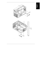
Chapter 3
Installing LH 4 Components
20
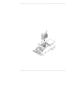
Figure 3-5. Removing the Memory Cards
3.
Position the memory board on a static-dissipating work surface and remove
the DIMMs from their packing materials.
4.
Remove a DIMM from its container, handling the module by its ends; do
not touch the pins. Lay it on an anti-static surface.
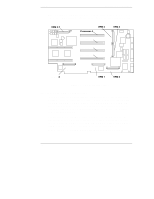
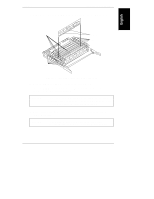
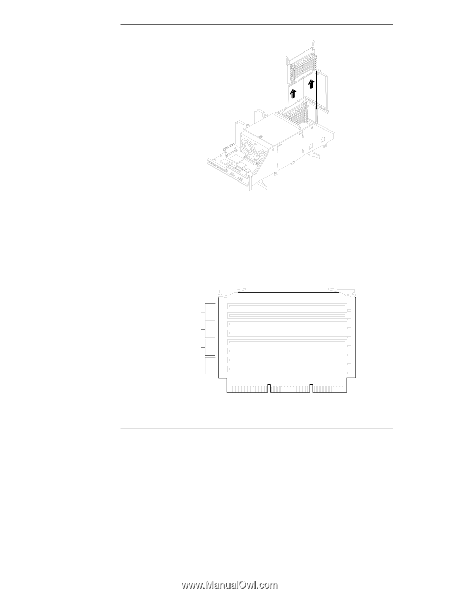
5.
Locate the slot in which you will install the DIMM (shown in Figure 3-6).
Spread the two retaining clips outward (see Figure 3-7).
J1
J2
J3
J4
J5
J6
J7
J8
Bank 1
Bank 2
Bank 3
Bank 4
Figure 3-6. DIMM Slot Location