HP LH4r HP Netserver LH 3/LH 3r to LH 4/LH 4r - Page 22
Installing Processors
 |
View all HP LH4r manuals
Add to My Manuals
Save this manual to your list of manuals |
Page 22 highlights
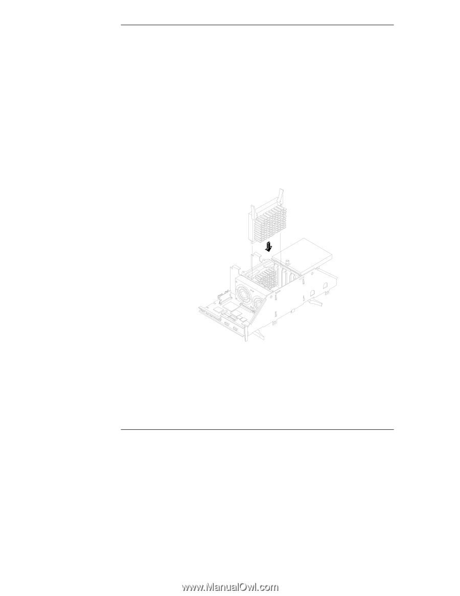
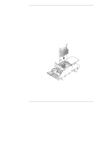
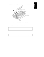
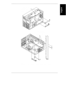
Chapter 3 Installing LH 4 Components Installing Processors 1. Position the LH 4 CPU baseboard, as shown in Figure 3-3, on an anti-static mat. 2. Unfasten the two captive screws securing the processor cage cover, then lift it off and put it aside. You will see two empty slots for processors 1 and 2, and two terminators installed in slots processor 3 and processor 4. 3. Open the levers at the top of the processor, as shown in Figure 3-3. 4. Insert a processor in the processor 1 slot until it is completely in. 5. Push the levers inward to close them. This also locks the processor into place. 6. Open the levers on the second processor, insert it into the slot immediately above the first processor, as shown in Figure 3-3, and close the levers. Figure 3-3. Installing Processors in Processor Cage 18
-
 1
1 -
2
-
3
-
4
-
5
-
6
-
7
-
8
-
9
-
10
-
11
-
12
-
13
-
14
-
15
-
16
-
 17
17 -
 18
18 -
 19
19 -
 20
20 -
 21
21 -
 22
22 -
 23
23 -
 24
24 -
 25
25 -
 26
26 -
 27
27 -
28
-
29
-
30
-
31
-
32
-
33
-
34
-
35
-
36
-
37
-
38
-
39
-
40
-
41
-
42
 |
 |