HP LaserJet P1500 Service Manual - Page 37
Internal components
 |
View all HP LaserJet P1500 manuals
Add to My Manuals
Save this manual to your list of manuals |
Page 37 highlights
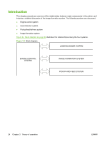
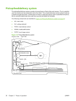
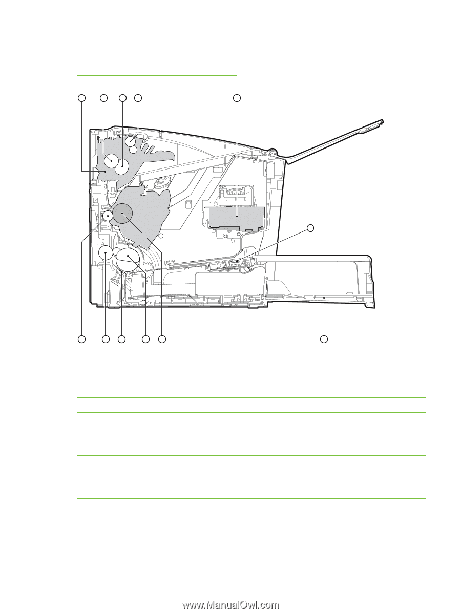
Internal components Figure 3-2 Cross-section of printer on page 25 highlights the major internal components. Figure 3-2 Cross-section of printer 1 2 34 5 12 11 10 98 1 Fusing unit 2 Pressure roller 3 Fusing sleeve 4 Delivery roller 5 Laser/scanner unit 6 Single-sheet-feed slot 7 Multi-purpose tray 8 Photosensitive drum 9 Pickup roller 10 Separation pad 11 Feed roller 12 Transfer roller ENWW 6 7 Internal components 25
-
 1
1 -
2
-
3
-
4
-
5
-
6
-
7
-
8
-
9
-
10
-
11
-
12
-
13
-
14
-
15
-
16
-
17
-
18
-
19
-
20
-
21
-
22
-
23
-
24
-
25
-
26
-
27
-
28
-
29
-
30
-
31
-
 32
32 -
 33
33 -
 34
34 -
 35
35 -
 36
36 -
 37
37 -
 38
38 -
 39
39 -
 40
40 -
 41
41 -
 42
42 -
43
-
44
-
45
-
46
-
47
-
48
-
49
-
50
-
51
-
52
-
53
-
54
-
55
-
56
-
57
-
58
-
59
-
60
-
61
-
62
-
63
-
64
-
65
-
66
-
67
-
68
-
69
-
70
-
71
-
72
-
73
-
74
-
75
-
76
-
77
-
78
-
79
-
80
-
81
-
82
-
83
-
84
-
85
-
86
-
87
-
88
-
89
-
90
-
91
-
92
-
93
-
94
-
95
-
96
-
97
-
98
-
99
-
100
-
101
-
102
-
103
-
104
-
105
-
106
-
107
-
108
-
109
-
110
-
111
-
112
-
113
-
114
-
115
-
116
-
117
-
118
-
119
-
120
-
121
-
122
-
123
-
124
-
125
-
126
-
127
-
128
-
129
-
130
-
131
-
132
-
133
-
134
-
135
-
136
-
137
-
138
-
139
-
140
-
141
-
142
-
143
-
144
-
145
-
146
-
147
-
148
-
149
-
150
 |
 |
Internal components
Figure
3
-
2
Cross-section of printer
on page
25
highlights the major internal components.
Figure 3-2
Cross-section of printer
1
2
3
4
5
6
7
8
9
10
11
12
1
Fusing unit
2
Pressure roller
3
Fusing sleeve
4
Delivery roller
5
Laser/scanner unit
6
Single-sheet-feed slot
7
Multi-purpose tray
8
Photosensitive drum
9
Pickup roller
10
Separation pad
11
Feed roller
12
Transfer roller
ENWW
Internal components
25