HP Mini 1000 HP Mini 1000 and Compaq Mini 700 - Maintenance and Service Guide - Page 53
Top cover, The two front covers are short in height and are notched to prevent incorrect insertion. - power short
 |
View all HP Mini 1000 manuals
Add to My Manuals
Save this manual to your list of manuals |
Page 53 highlights
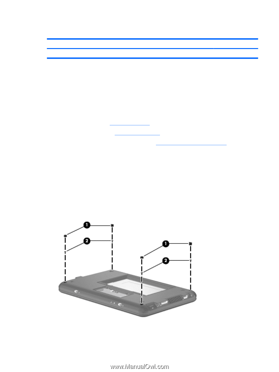
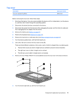
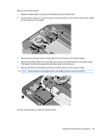
Top cover Description Top cover (includes TouchPad) Spare part number 504612-001 Before removing the top cover, follow these steps: 1. Shut down the device. If you are unsure whether the device is off or in Hibernation, turn the device on, and then shut it down through the operating system. 2. Disconnect all external devices connected to the device. 3. Disconnect the power from the device by first unplugging the power cord from the AC outlet and then unplugging the AC adapter from the device. 4. Remove the battery (see Battery on page 37). 5. Remove the keyboard (see Keyboard on page 40). 6. Remove the hard drive or solid-state drive (see Mass storage devices on page 42). 1. Turn the device upside down, with the front toward you. 2. Use a thin, flat tool to remove the four screw covers (1). There are three different variations of the covers, each of which is shaped like a rounded square: ● The two front covers are short in height and are notched to prevent incorrect insertion. ● The right rear cover is taller in height and is notched. ● The left rear cover is taller in height and is not notched. 3. Remove the four Phillips PM2.5×7.0 screws (2) that secure the top cover to the base enclosure. 4. Turn the device right-side up, with the front toward you. Component replacement procedures 45
-
 1
1 -
2
-
3
-
4
-
5
-
6
-
7
-
8
-
9
-
10
-
11
-
12
-
13
-
14
-
15
-
16
-
17
-
18
-
19
-
20
-
21
-
22
-
23
-
24
-
25
-
26
-
27
-
28
-
29
-
30
-
31
-
32
-
33
-
34
-
35
-
36
-
37
-
38
-
39
-
40
-
41
-
42
-
43
-
44
-
45
-
46
-
47
-
 48
48 -
 49
49 -
 50
50 -
 51
51 -
 52
52 -
 53
53 -
 54
54 -
 55
55 -
 56
56 -
 57
57 -
 58
58 -
59
-
60
-
61
-
62
-
63
-
64
-
65
-
66
-
67
-
68
-
69
-
70
-
71
-
72
-
73
-
74
-
75
-
76
-
77
-
78
-
79
-
80
-
81
-
82
-
83
-
84
-
85
-
86
-
87
-
88
-
89
-
90
-
91
-
92
-
93
-
94
-
95
-
96
-
97
-
98
-
99
-
100
-
101
-
102
-
103
-
104
-
105
-
106
-
107
-
108
-
109
-
110
-
111
-
112
-
113
-
114
-
115
-
116
-
117
-
118
-
119
-
120
-
121
 |
 |