HP Mini 1000 HP Mini 1000 and Compaq Mini 700 - Maintenance and Service Guide - Page 69
USB board and internal display switch, from the USB board.
 |
View all HP Mini 1000 manuals
Add to My Manuals
Save this manual to your list of manuals |
Page 69 highlights
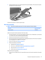
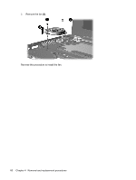
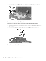
USB board and internal display switch NOTE: The internal display switch module is included in the Cable Kit, spare part number 507708-001. Description USB board Spare part number 506336-001 Before removing the USB board, follow these steps: 1. Shut down the computer. If you are unsure whether the computer is off or in Hibernation, turn the computer on, and then shut it down through the operating system. 2. Disconnect all external devices connected to the computer. 3. Disconnect the power from the computer by first unplugging the power cord from the AC outlet and then unplugging the AC Adapter from the computer. 4. Remove the battery (see Battery on page 37). 5. Remove the following components: a. Keyboard (see Keyboard on page 40). b. Hard drive (see Mass storage devices on page 42). c. Top cover (see Top cover on page 45). d. Fan (see Fan on page 59). Remove the USB board: 1. Disconnect the internal display switch cable (1) from the USB board. 2. Remove the Phillips PM2.0×3.0 screw (2) that secures the DC jack bracket to the base enclosure. 3. Remove the DC jack bracket (1) and USB board (2) from the base enclosure. Component replacement procedures 61
-
 1
1 -
2
-
3
-
4
-
5
-
6
-
7
-
8
-
9
-
10
-
11
-
12
-
13
-
14
-
15
-
16
-
17
-
18
-
19
-
20
-
21
-
22
-
23
-
24
-
25
-
26
-
27
-
28
-
29
-
30
-
31
-
32
-
33
-
34
-
35
-
36
-
37
-
38
-
39
-
40
-
41
-
42
-
43
-
44
-
45
-
46
-
47
-
48
-
49
-
50
-
51
-
52
-
53
-
54
-
55
-
56
-
57
-
58
-
59
-
60
-
61
-
62
-
63
-
 64
64 -
 65
65 -
 66
66 -
 67
67 -
 68
68 -
 69
69 -
 70
70 -
 71
71 -
 72
72 -
 73
73 -
 74
74 -
75
-
76
-
77
-
78
-
79
-
80
-
81
-
82
-
83
-
84
-
85
-
86
-
87
-
88
-
89
-
90
-
91
-
92
-
93
-
94
-
95
-
96
-
97
-
98
-
99
-
100
-
101
-
102
-
103
-
104
-
105
-
106
-
107
-
108
-
109
-
110
-
111
-
112
-
113
-
114
-
115
-
116
-
117
-
118
-
119
-
120
-
121
 |
 |