HP Mini 1000 HP Mini 1000 and Compaq Mini 700 - Maintenance and Service Guide - Page 70
and module, from the base enclosure.
 |
View all HP Mini 1000 manuals
Add to My Manuals
Save this manual to your list of manuals |
Page 70 highlights
4. Detach the SIM card cable (3). The SIM card cable is attached to the battery bay with tape. Reverse this procedure to install the USB board. If it is necessary to replace the internal display switch module, perform the following steps: 1. Remove the Phillips PM2.0×3.0 screw (1) that secures the internal display switch bracket to the base enclosure. 2. Remove the internal display switch bracket (2) and module (3) from the base enclosure. Reverse this procedure to install the internal display switch. 62 Chapter 4 Removal and replacement procedures
-
 1
1 -
2
-
3
-
4
-
5
-
6
-
7
-
8
-
9
-
10
-
11
-
12
-
13
-
14
-
15
-
16
-
17
-
18
-
19
-
20
-
21
-
22
-
23
-
24
-
25
-
26
-
27
-
28
-
29
-
30
-
31
-
32
-
33
-
34
-
35
-
36
-
37
-
38
-
39
-
40
-
41
-
42
-
43
-
44
-
45
-
46
-
47
-
48
-
49
-
50
-
51
-
52
-
53
-
54
-
55
-
56
-
57
-
58
-
59
-
60
-
61
-
62
-
63
-
64
-
 65
65 -
 66
66 -
 67
67 -
 68
68 -
 69
69 -
 70
70 -
 71
71 -
 72
72 -
 73
73 -
 74
74 -
 75
75 -
76
-
77
-
78
-
79
-
80
-
81
-
82
-
83
-
84
-
85
-
86
-
87
-
88
-
89
-
90
-
91
-
92
-
93
-
94
-
95
-
96
-
97
-
98
-
99
-
100
-
101
-
102
-
103
-
104
-
105
-
106
-
107
-
108
-
109
-
110
-
111
-
112
-
113
-
114
-
115
-
116
-
117
-
118
-
119
-
120
-
121
 |
 |
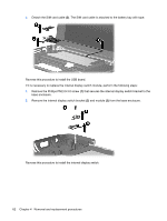
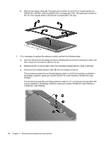
4.
Detach the SIM card cable
(3)
. The SIM card cable is attached to the battery bay with tape.
Reverse this procedure to install the USB board.
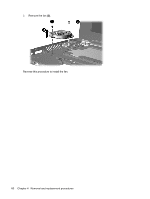
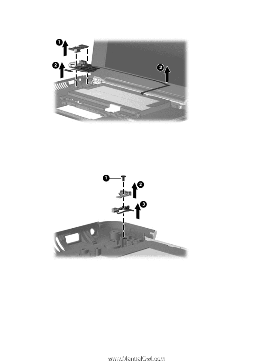
If it is necessary to replace the internal display switch module, perform the following steps:
1.
Remove the Phillips PM2.0×3.0 screw
(1)
that secures the internal display switch bracket to the
base enclosure.
2.
Remove the internal display switch bracket
(2)
and module
(3)
from the base enclosure.
Reverse this procedure to install the internal display switch.
62
Chapter 4
Removal and replacement procedures