HP Mini 1000 HP Mini 1000 and Compaq Mini 700 - Maintenance and Service Guide - Page 57
Remove the Phillips PM2.0×3.0 screw, Remove the WLAN module
 |
View all HP Mini 1000 manuals
Add to My Manuals
Save this manual to your list of manuals |
Page 57 highlights
Remove the WLAN module: 1. Detach the black Mylar covering (not illustrated) that surrounds the fan. 2. Several system cables are routed through a channel between the fan and the battery bay. Detach the black tape from the cables. 3. Disconnect the wireless antenna cables (1) from the terminals on the WLAN module. 4. Remove the Phillips PM2.0×3.0 screw (2) that secures the WLAN module to the system board. (The edge of the module opposite the slot rises away from the device.) 5. Remove the WLAN module (3) by pulling the module away from the slot at an angle. NOTE: WLAN modules are designed with a notch (4) to prevent incorrect insertion. Reverse this procedure to install the WLAN module. Component replacement procedures 49
-
 1
1 -
2
-
3
-
4
-
5
-
6
-
7
-
8
-
9
-
10
-
11
-
12
-
13
-
14
-
15
-
16
-
17
-
18
-
19
-
20
-
21
-
22
-
23
-
24
-
25
-
26
-
27
-
28
-
29
-
30
-
31
-
32
-
33
-
34
-
35
-
36
-
37
-
38
-
39
-
40
-
41
-
42
-
43
-
44
-
45
-
46
-
47
-
48
-
49
-
50
-
51
-
 52
52 -
 53
53 -
 54
54 -
 55
55 -
 56
56 -
 57
57 -
 58
58 -
 59
59 -
 60
60 -
 61
61 -
 62
62 -
63
-
64
-
65
-
66
-
67
-
68
-
69
-
70
-
71
-
72
-
73
-
74
-
75
-
76
-
77
-
78
-
79
-
80
-
81
-
82
-
83
-
84
-
85
-
86
-
87
-
88
-
89
-
90
-
91
-
92
-
93
-
94
-
95
-
96
-
97
-
98
-
99
-
100
-
101
-
102
-
103
-
104
-
105
-
106
-
107
-
108
-
109
-
110
-
111
-
112
-
113
-
114
-
115
-
116
-
117
-
118
-
119
-
120
-
121
 |
 |

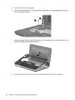
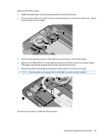
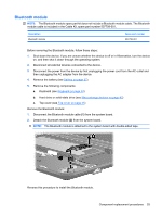
Remove the WLAN module:
1.
Detach the black Mylar covering (not illustrated) that surrounds the fan.
2.
Several system cables are routed through a channel between the fan and the battery bay. Detach
the black tape from the cables.
3.
Disconnect the wireless antenna cables
(1)
from the terminals on the WLAN module.
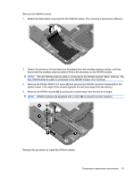
4.
Remove the Phillips PM2.0×3.0 screw
(2)
that secures the WLAN module to the system board.
(The edge of the module opposite the slot rises away from the device.)
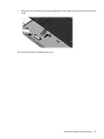
5.
Remove the WLAN module
(3)
by pulling the module away from the slot at an angle.
NOTE:
WLAN modules are designed with a notch
(4)
to prevent incorrect insertion.
Reverse this procedure to install the WLAN module.
Component replacement procedures
49