HP Mini 1000 HP Mini 1000 and Compaq Mini 700 - Maintenance and Service Guide - Page 67
Fan, Remove the fan
 |
View all HP Mini 1000 manuals
Add to My Manuals
Save this manual to your list of manuals |
Page 67 highlights
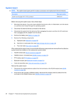
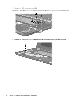
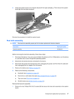
Fan Description Fan Spare part number 504615-001 NOTE: To properly ventilate the device, allow at least a 7.6-cm (3-inch) clearance on the left side of the device. The device uses an electric fan for ventilation. The fan is controlled by a temperature sensor and is designed to turn on automatically when high temperature conditions exist. These conditions are affected by high external temperatures, system power consumption, power management/battery conservation configurations, battery fast charging, and software requirements. Exhaust air is displaced through the ventilation grill located on the left side of the device. Before removing the fan, follow these steps: 1. Shut down the device. If you are unsure whether the device is off or in Hibernation, turn the device on, and then shut it down through the operating system. 2. Disconnect all external devices connected to the device. 3. Disconnect the power from the device by first unplugging the power cord from the AC outlet and then unplugging the AC adapter from the device. 4. Remove the battery (see Battery on page 37). 5. Remove the following components: a. Keyboard (see Keyboard on page 40) b. Hard drive or solid-state drive (see Mass storage devices on page 42) c. Top cover (see Top cover on page 45) d. System board (see System board on page 54) Remove the fan: 1. Detach the black mylar covering and tape (see WLAN module on page 48), and then move the cables aside. 2. Remove the Phillips PM2.0×3.0 screw (1) and the Phillips PM2.0×4.5 screw (2) that secure the fan to the base enclosure. Component replacement procedures 59
-
 1
1 -
2
-
3
-
4
-
5
-
6
-
7
-
8
-
9
-
10
-
11
-
12
-
13
-
14
-
15
-
16
-
17
-
18
-
19
-
20
-
21
-
22
-
23
-
24
-
25
-
26
-
27
-
28
-
29
-
30
-
31
-
32
-
33
-
34
-
35
-
36
-
37
-
38
-
39
-
40
-
41
-
42
-
43
-
44
-
45
-
46
-
47
-
48
-
49
-
50
-
51
-
52
-
53
-
54
-
55
-
56
-
57
-
58
-
59
-
60
-
61
-
 62
62 -
 63
63 -
 64
64 -
 65
65 -
 66
66 -
 67
67 -
 68
68 -
 69
69 -
 70
70 -
 71
71 -
 72
72 -
73
-
74
-
75
-
76
-
77
-
78
-
79
-
80
-
81
-
82
-
83
-
84
-
85
-
86
-
87
-
88
-
89
-
90
-
91
-
92
-
93
-
94
-
95
-
96
-
97
-
98
-
99
-
100
-
101
-
102
-
103
-
104
-
105
-
106
-
107
-
108
-
109
-
110
-
111
-
112
-
113
-
114
-
115
-
116
-
117
-
118
-
119
-
120
-
121
 |
 |