HP Mini 110-4100ca HP Mini 200 - Maintenance and Service Guide - Page 70
Display assembly
 |
View all HP Mini 110-4100ca manuals
Add to My Manuals
Save this manual to your list of manuals |
Page 70 highlights
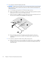
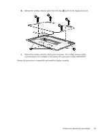
Display assembly NOTE: The display assembly spare part kit includes the display panel cable, 2 WLAN antenna transceivers and cables, and a webcamera/microphone module and cable. Description In gloss black finish In Pacific blue finish In Sonoma red finish WSVGA, HD display assembly in gloss black finish for use only on computer models equipped with WWAN capability (includes WWAN antenna cables and transceivers) Spare part number 658507-001 658510-001 658508-001 668166-001 Before removing the display assembly, follow these steps: 1. Shut down the computer. If you are unsure whether the computer is off or in Hibernation, turn the computer on, and then shut it down through the operating system. 2. Disconnect all external devices connected to the computer. 3. Disconnect the power from the computer by first unplugging the power cord from the AC outlet and then unplugging the AC adapter from the computer. 4. Remove the battery (see Battery on page 34), and then remove the following components: ● Service cover (see WLAN module on page 36) ● Keyboard (see Keyboard on page 45) ● Top cover (see Top cover on page 48) Remove the display assembly: 1. Position the computer upside down, with the front toward you. CAUTION: Support the open display assembly when removing the following screws. Failure to support the display assembly can result in damage to the display assembly and other computer components. 2. Remove the two Phillips PM2.0×5.7 screws (1) that secure the display assembly to the computer. 62 Chapter 4 Removal and replacement procedures
-
 1
1 -
2
-
3
-
4
-
5
-
6
-
7
-
8
-
9
-
10
-
11
-
12
-
13
-
14
-
15
-
16
-
17
-
18
-
19
-
20
-
21
-
22
-
23
-
24
-
25
-
26
-
27
-
28
-
29
-
30
-
31
-
32
-
33
-
34
-
35
-
36
-
37
-
38
-
39
-
40
-
41
-
42
-
43
-
44
-
45
-
46
-
47
-
48
-
49
-
50
-
51
-
52
-
53
-
54
-
55
-
56
-
57
-
58
-
59
-
60
-
61
-
62
-
63
-
64
-
 65
65 -
 66
66 -
 67
67 -
 68
68 -
 69
69 -
 70
70 -
 71
71 -
 72
72 -
 73
73 -
 74
74 -
 75
75 -
76
-
77
-
78
-
79
-
80
-
81
-
82
-
83
-
84
-
85
-
86
-
87
-
88
-
89
-
90
-
91
-
92
-
93
-
94
-
95
 |
 |
