HP Model 712/100 hp 9000 series 700 model 712 technical reference manual (a261 - Page 26
SCSI-2, Table 2-5. Recommended SCSI-2 Bus Addresses, Table 2-6. SCSI-2 Interface Technical Information
 |
View all HP Model 712/100 manuals
Add to My Manuals
Save this manual to your list of manuals |
Page 26 highlights
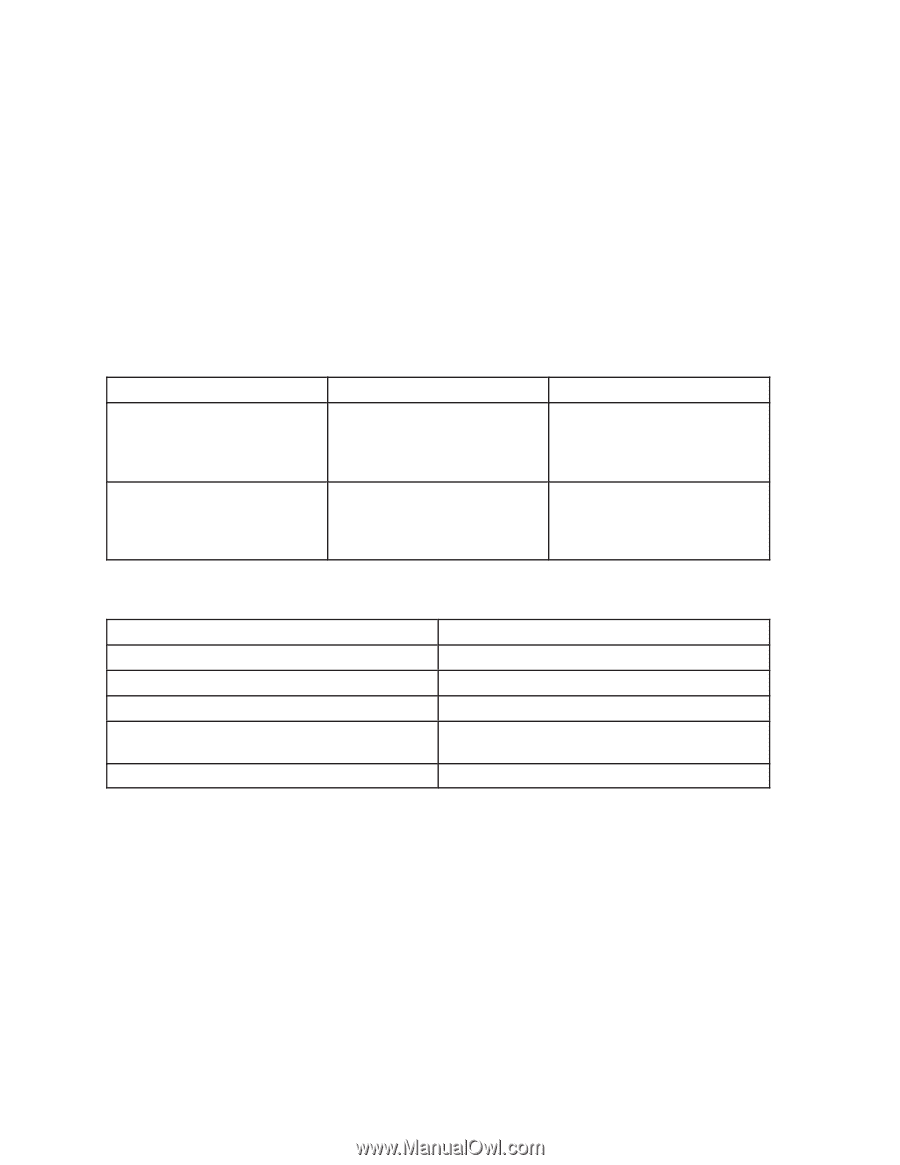
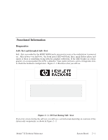
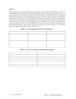
SCSI-2 The primary function of the SCSI-2 interface circuit is to take data from the CPU bus, translate it to SCSI format, and transmit it down the SCSI bus to a mass storage device, and vice versa. A secondary function is to keep track of the status of the SCSI bus and inform the CPU of the status. SCSI circuits must have terminating resistors installed on them. When using the external SCSI configuration, you must use an active SCSI terminator at the last external device on the SCSI bus. All other devices, external or internal, must not be terminated. If your workstation contains the external cable but you have no external devices, the terminator need not be installed in the rear-panel SCSI connector. Use only HP K2291 terminators to ensure reliable system operation. Recommended SCSI-2 mass storage device bus addresses are listed in Table 2-5., and SCSI interface technical information is listed in Table 2-6. Table 2-5. Recommended SCSI-2 Bus Addresses Application High Use/Priority Other devices Medium Use/Priority Optional Use Low Use/Priority Unit or Mass Storage Device CPU Root Hard Disk Drive Most Used Hard Disk Drive Least Used Hard Disk Drive DDS Tape Drives CD ROM Disk Drives (the 712 will not support a SCSI Floppy) Recommended Bus Address 7 6 5 4 3 2 1 0 Table 2-6. SCSI-2 Interface Technical Information Type: Data rate: Device limits: Connector type: Function Maximum external cable length: Data SCSI-II (ANSI X3.131-1986), single-ended Synchronous - 5 MBs/second 7 internal and/or external peripherals SCSI-II, ALT-1 50-pin high-density thumbscrew 4 meters (13.1 feet) 2-6 System Board Model 712 Technical Reference
-
 1
1 -
2
-
3
-
4
-
5
-
6
-
7
-
8
-
9
-
10
-
11
-
12
-
13
-
14
-
15
-
16
-
17
-
18
-
19
-
20
-
 21
21 -
 22
22 -
 23
23 -
 24
24 -
 25
25 -
 26
26 -
 27
27 -
 28
28 -
 29
29 -
 30
30 -
 31
31 -
32
-
33
-
34
-
35
-
36
-
37
-
38
-
39
-
40
-
41
-
42
-
43
-
44
-
45
-
46
-
47
-
48
-
49
-
50
-
51
-
52
-
53
-
54
-
55
-
56
-
57
-
58
-
59
-
60
-
61
-
62
-
63
-
64
-
65
-
66
-
67
-
68
-
69
-
70
-
71
-
72
-
73
-
74
-
75
-
76
-
77
-
78
-
79
-
80
-
81
-
82
-
83
-
84
-
85
-
86
-
87
-
88
-
89
-
90
-
91
-
92
-
93
-
94
 |
 |