HP Model 712/100 hp 9000 series 700 model 712 technical reference manual (a261 - Page 45
HP A4015A X.25/Serial Card, Table 3-4., X.25 Connector Pinouts, Table 3-5. RS-232 Connector Pinouts
 |
View all HP Model 712/100 manuals
Add to My Manuals
Save this manual to your list of manuals |
Page 45 highlights
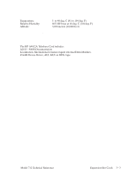
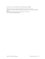
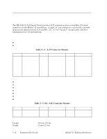
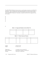
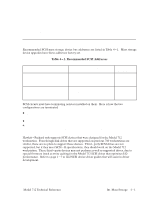
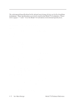
HP A4015A X.25/Serial Card Description The HP A4015A X.25/Serial Card, provides a X.25 connection and a second RS-232 serial connection to the Model 712 workstation. A single 26-pin connector is used on the card with all necessary signals for both X.25 and RS-232. A "two-headed" external cable will allow simultaneous use of both functions. Features X.25 H X.25 supports 1.2 to 19kbs. H X.25 supports implementation of the LAP-B data-link protocol Table 3-4. X.25 Connector Pinouts Pin No. 1 2 3 4 5 6 7 8 9 Signal Prot. Ground TXD RXD RTS CTS DSR Signal Ground DCD Not Connected Pin No. 10 11 12 13 14 15 16 17 Signal Not Connected Not Connected Not Connected Not Connected Not Connected TCLK Not Connected RCLK Pin No. 18 19 20 21 22 23 24 25 Signal Not Connected Not Connected DTR Not Connected Not Connected Not Connected TTE Not Connected Serial H EIA RS-232-C (CCITT V.28/V.24 460.8 Kbps with CTS/RTS) compatibility H Modem control H Supports data transfer rates up to 454k baud H Software selectable parity configuration H Software selectable baud rate H Interrupt capability through status or modem signal lines H 9-pin male D-sub connector Table 3-5. RS-232 Connector Pinouts Pin No. 1 2 3 Signal DCD RXD TXD Physical Specifications Length: Height: Pin No. 4 5 6 Signal DTR Ground DSR 193 mm (7.6 in) 64 mm (2.5 in) Pin No. 7 8 9 Signal RTS CTS RI 3-8 Expansion Slot Cards Model 712 Technical Reference
-
 1
1 -
2
-
3
-
4
-
5
-
6
-
7
-
8
-
9
-
10
-
11
-
12
-
13
-
14
-
15
-
16
-
17
-
18
-
19
-
20
-
21
-
22
-
23
-
24
-
25
-
26
-
27
-
28
-
29
-
30
-
31
-
32
-
33
-
34
-
35
-
36
-
37
-
38
-
39
-
 40
40 -
 41
41 -
 42
42 -
 43
43 -
 44
44 -
 45
45 -
 46
46 -
 47
47 -
 48
48 -
 49
49 -
 50
50 -
51
-
52
-
53
-
54
-
55
-
56
-
57
-
58
-
59
-
60
-
61
-
62
-
63
-
64
-
65
-
66
-
67
-
68
-
69
-
70
-
71
-
72
-
73
-
74
-
75
-
76
-
77
-
78
-
79
-
80
-
81
-
82
-
83
-
84
-
85
-
86
-
87
-
88
-
89
-
90
-
91
-
92
-
93
-
94
 |
 |