HP Model 712/100 hp 9000 series 700 model 712 technical reference manual (a261 - Page 68
Electrical Information, START_PWR_DOWN_L, POWER_ON_L, 5 Volt, Ground, 3.3 Volt, 5 Volt SCSI, white
 |
View all HP Model 712/100 manuals
Add to My Manuals
Save this manual to your list of manuals |
Page 68 highlights
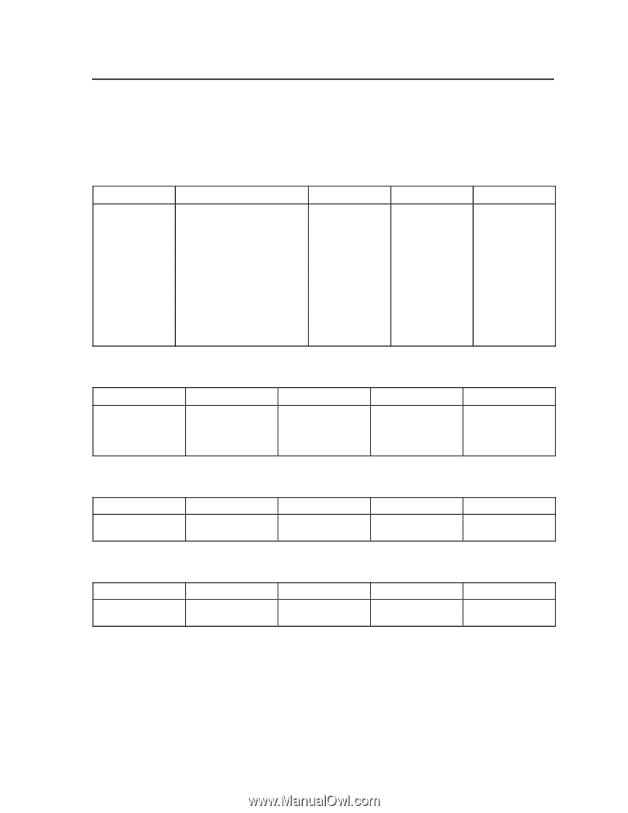
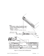
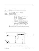
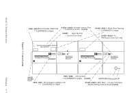
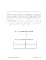
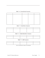
Electrical Information Connector Pinouts Table 7-4. System Board Connector Terminal 1 2 3 4 5 6 7 8 9 10 11 Voltage/Signal START_PWR_DOWN_L POWER_ON_L +5 Volt Ground +12 Volt Ground +5 Volt +3.3 Volt +5 Volt (SCSI) Ground +5 Volt Wire Gauge 22 22 18 18 18 18 18 18 18 18 18 Color white blue orange black red black orange yellow violet black orange Table 7-5. Hard Drive Connector Terminal 1 2 3 4 Voltage/Signal +12 Volt Ground Ground +5 Volt Wire Gauge 22 22 22 22 Color red black black orange Table 7-6. Flexible Disk Drive Connector Terminal 1 2 Voltage/Signal +5 Volt Ground Wire Gauge 22 22 Color orange black Table 7-7. LED Connector Terminal 1 2 Voltage/Signal Wire Gauge Color Cathode (-) Anode (+) N/A N/A N/A N/A Note: Load Current values are maximums. Load Current N/A N/A 3.2 3.6 0.15 3.6 3.2 1.0 0.5 3.6 3.2 Load Current 0.7 0.85 0.85 1.0 Load Current 0.8 0.8 Load Current 0.01 0.01 Model 712 Technical Reference Power Supply 7-3
-
 1
1 -
2
-
3
-
4
-
5
-
6
-
7
-
8
-
9
-
10
-
11
-
12
-
13
-
14
-
15
-
16
-
17
-
18
-
19
-
20
-
21
-
22
-
23
-
24
-
25
-
26
-
27
-
28
-
29
-
30
-
31
-
32
-
33
-
34
-
35
-
36
-
37
-
38
-
39
-
40
-
41
-
42
-
43
-
44
-
45
-
46
-
47
-
48
-
49
-
50
-
51
-
52
-
53
-
54
-
55
-
56
-
57
-
58
-
59
-
60
-
61
-
62
-
 63
63 -
 64
64 -
 65
65 -
 66
66 -
 67
67 -
 68
68 -
 69
69 -
 70
70 -
 71
71 -
 72
72 -
 73
73 -
74
-
75
-
76
-
77
-
78
-
79
-
80
-
81
-
82
-
83
-
84
-
85
-
86
-
87
-
88
-
89
-
90
-
91
-
92
-
93
-
94
 |
 |