HP Model 712/100 hp 9000 series 700 model 712 technical reference manual (a261 - Page 31
Connector Pinouts, Slot Connectors
 |
View all HP Model 712/100 manuals
Add to My Manuals
Save this manual to your list of manuals |
Page 31 highlights
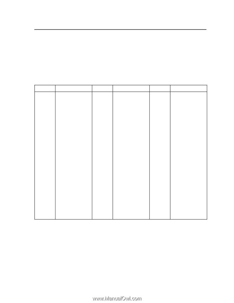
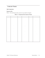
Connector Pinouts Slot Connectors Expansion Slot Table 2-7 lists the Expansion Slot connector's pin numbers and signals. Table 2-7. Expansion Slot Connector Pinout Pin No. A1 A2 A3 A4 A5 A6 A7 A8 A9 A10 A11 A12 A13 A14 A15 A16 A17 A18 A19 A20 A21 A22 A23 A24 A25 A26 A27 Signal EPR_D[2] Ground Spare2 Ground Spare3 Ground GSC[6] GSC[7] GSC[8] VDD GSC[12] GSC[13] GSC[14] Ground GSC[18] GSC[19] GSC[20] VDD GSC[24] GSC[25] GSC[26] Ground GSC[30] GSC[31] VDD TYPE[1] TYPE[0] Pin No. A28 A29 A30 A31 A32 A33 A34 A35 A36 A37 A38 A39 A40 B1 B2 B3 B4 B5 B6 B7 B8 B9 B10 B11 B12 B13 B14 Signal Ground ADDV_L EGRANT_L EREQUEST_L VDD LS_L INTERRUPT_L ART2EXP Ground SYNC4H Ground SYNC4L Ground GSC[0] GSC[1] GSC[2] VDD GSC[3] GSC[4] GSC[5] Ground GSC[9] GSC[10] GSC[11] VDD GSC[15] GSC[16] Pin No. B15 B16 B17 B18 B19 B20 B21 B22 B23 B24 B25 B26 B27 B28 B29 B30 B31 B32 B33 B34 B35 B36 B37 B38 B39 B40 Signal GSC[17] Ground GSC[21] GSC[22] GSC[23] VDD GSC[27] GSC[28] GSC[29] Ground TYPE[3] TYPE[2] PARITY VDL ERROR_L READY_L EXP_RESET_L Ground EXP2CON TMS TCK PWR_RST_L VDL Ground XQL p12V Model 712 Technical Reference System Board 2-11
-
 1
1 -
2
-
3
-
4
-
5
-
6
-
7
-
8
-
9
-
10
-
11
-
12
-
13
-
14
-
15
-
16
-
17
-
18
-
19
-
20
-
21
-
22
-
23
-
24
-
25
-
 26
26 -
 27
27 -
 28
28 -
 29
29 -
 30
30 -
 31
31 -
 32
32 -
 33
33 -
 34
34 -
 35
35 -
 36
36 -
37
-
38
-
39
-
40
-
41
-
42
-
43
-
44
-
45
-
46
-
47
-
48
-
49
-
50
-
51
-
52
-
53
-
54
-
55
-
56
-
57
-
58
-
59
-
60
-
61
-
62
-
63
-
64
-
65
-
66
-
67
-
68
-
69
-
70
-
71
-
72
-
73
-
74
-
75
-
76
-
77
-
78
-
79
-
80
-
81
-
82
-
83
-
84
-
85
-
86
-
87
-
88
-
89
-
90
-
91
-
92
-
93
-
94
 |
 |