HP Model 712/100 hp 9000 series 700 model 712 technical reference manual (a261 - Page 33
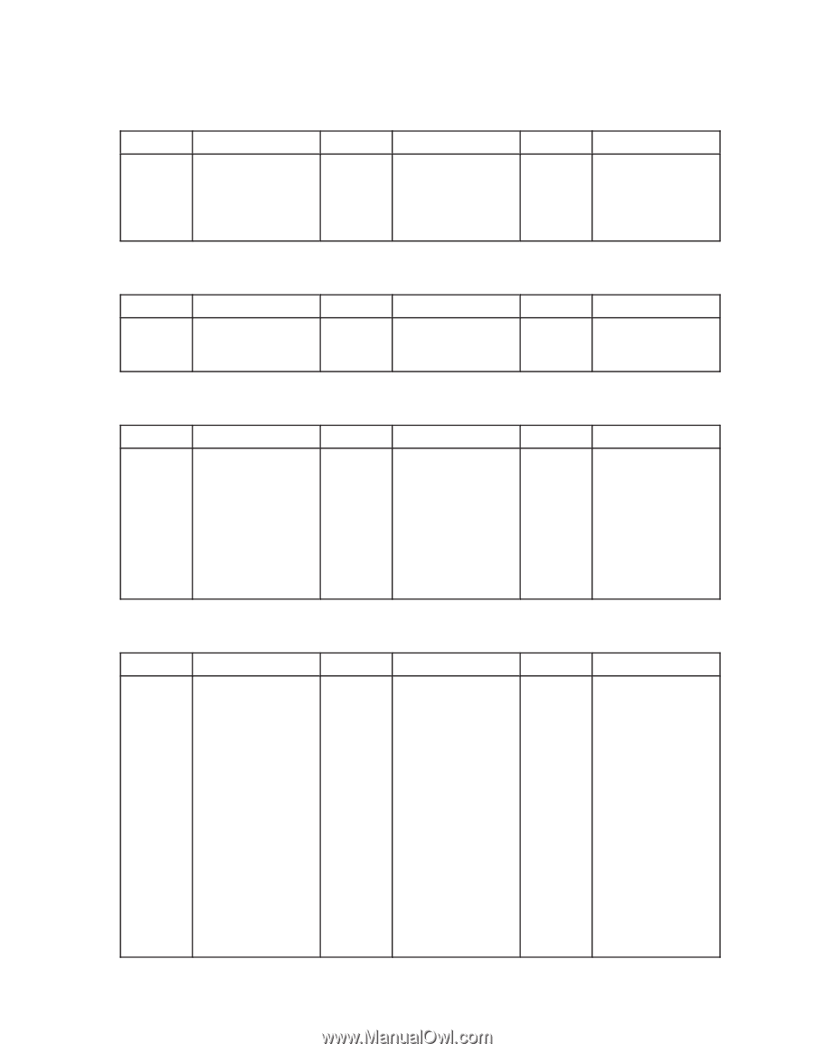
Table 2-12. Video Connector Pinouts, Table 2-13. RS-232 Connector Pinouts, Table 2-14. HP Parallel
 |
View all HP Model 712/100 manuals
Add to My Manuals
Save this manual to your list of manuals |
Page 33 highlights
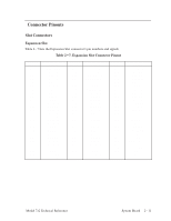
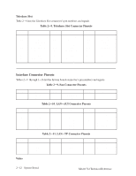
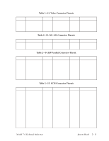
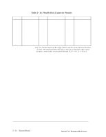
Pin No. 1 2 3 4 5 Pin No. 1 2 3 Pin No. 1 2 3 4 5 6 7 8 9 Pin No. 1 2 3 4 5 6 7 8 9 10 11 12 13 14 15 16 17 Table 2-12. Video Connector Pinouts Signal Red Green Blue Reserved Digital Ground Pin No. 6 7 8 9 10 Signal Analog Ground Analog Ground Analog Ground (No Connect) Digital Ground Pin No. 11 12 13 14 15 Table 2-13. RS-232 Connector Pinouts Signal (No Connect) (No Connect) Horizontal Sync Vertical Sync (No Connect) Signal DCD RXD TXD Pin No. 4 5 6 Signal DTR Ground DSR Pin No. 7 8 9 Table 2-14. HP Parallel Connector Pinout Signal RTS CTS RI Signal NSTROBE DATA0 DATA1 DATA2 DATA3 DATA4 DATA5 DATA6 DATA7 Pin No. 10 11 12 13 14 15 16 17 18 Signal NACK BUSY PE SLCT NAFD NERROR NINIT NSCT IN Ground Pin No. 19 20 21 22 23 24 25 26 27 Table 2-15. SCSI Connector Pinouts Signal Ground Ground Ground Ground Ground Ground Ground Ground (Shield) Ground (Shield) Signal Ground Ground Ground Ground Ground Ground Ground Ground Ground Ground Ground Ground NC Ground Ground Ground Ground Pin No. 18 19 20 21 22 23 24 25 26 27 28 29 30 31 32 33 34 Signal Ground Ground Ground Ground Ground Ground Ground Ground Data[0] Data[1] Data[2] Data[3] Data[4] Data[5] Data[6] Data[7] Data[P] Pin No. 35 36 37 38 39 40 41 42 43 44 45 46 47 48 49 50 Signal Ground Ground Ground +5V (VTerm) Ground Ground SCSI_ATN Ground SCSI_BSY SCSI_ACK SCSI_RST SCSI_MSG SCSI_SEL SCSI_CND SCSI_REQ SCSI_INO Model 712 Technical Reference System Board 2-13
-
 1
1 -
2
-
3
-
4
-
5
-
6
-
7
-
8
-
9
-
10
-
11
-
12
-
13
-
14
-
15
-
16
-
17
-
18
-
19
-
20
-
21
-
22
-
23
-
24
-
25
-
26
-
27
-
 28
28 -
 29
29 -
 30
30 -
 31
31 -
 32
32 -
 33
33 -
 34
34 -
 35
35 -
 36
36 -
 37
37 -
 38
38 -
39
-
40
-
41
-
42
-
43
-
44
-
45
-
46
-
47
-
48
-
49
-
50
-
51
-
52
-
53
-
54
-
55
-
56
-
57
-
58
-
59
-
60
-
61
-
62
-
63
-
64
-
65
-
66
-
67
-
68
-
69
-
70
-
71
-
72
-
73
-
74
-
75
-
76
-
77
-
78
-
79
-
80
-
81
-
82
-
83
-
84
-
85
-
86
-
87
-
88
-
89
-
90
-
91
-
92
-
93
-
94
 |
 |