HP Model 712/100 hp 9000 series 700 model 712 technical reference manual (a261 - Page 56
Table 4-4. SCSI Interface Signals, Model 712 Technical Reference, Int. Mass Storage
 |
View all HP Model 712/100 manuals
Add to My Manuals
Save this manual to your list of manuals |
Page 56 highlights
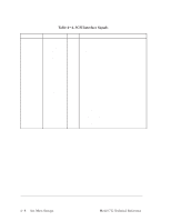
Connector Pinouts Table 4-4. SCSI Interface Signals Pin No. 02 04 06 08 10 12 14 16 18 20 22 24 26 28 30 32 34 36 38 40 42 44 46 48 50 Signal DB[0] DB[1] DB[2] DB[3] DB[4] DB[5] DB[6] DB[7] DB[P] To Description B Data Bus (LSB) B Data Bus B Data Bus B Data Bus B Data Bus B Data Bus B Data Bus B Data Bus (MSB) B Data Bus Parity Termpwr ATN BSY ACK RST MSG SEL C/D REQ I/O B Terminator Power Reserved Not Used (GND) D Indicates message available for drive Not Used (GND) B Signal indicating bus is in use D Data/Command transfer handshake D Or-tied signal indicating reset condition H Indicates message phase B Signal indicating selection/reselction phase H Indicates whether control or data info. is on data bus H DataCommand transfer handshake H Indicates direction of information transfer. Assertion indicates transfer to host. H = Host D = Drive B = Bidirectional Note: All odd pins shall be signal returns and shall be connected to signal GND at the drive, except pin 25 which is left free to protect against mis-insertion. 4-8 Int. Mass Storage Model 712 Technical Reference
-
 1
1 -
2
-
3
-
4
-
5
-
6
-
7
-
8
-
9
-
10
-
11
-
12
-
13
-
14
-
15
-
16
-
17
-
18
-
19
-
20
-
21
-
22
-
23
-
24
-
25
-
26
-
27
-
28
-
29
-
30
-
31
-
32
-
33
-
34
-
35
-
36
-
37
-
38
-
39
-
40
-
41
-
42
-
43
-
44
-
45
-
46
-
47
-
48
-
49
-
50
-
 51
51 -
 52
52 -
 53
53 -
 54
54 -
 55
55 -
 56
56 -
 57
57 -
 58
58 -
 59
59 -
 60
60 -
 61
61 -
62
-
63
-
64
-
65
-
66
-
67
-
68
-
69
-
70
-
71
-
72
-
73
-
74
-
75
-
76
-
77
-
78
-
79
-
80
-
81
-
82
-
83
-
84
-
85
-
86
-
87
-
88
-
89
-
90
-
91
-
92
-
93
-
94
 |
 |