HP NV517UT Maintenance & Service Guide: Compaq 500B and 505B Minitower Bus - Page 40
Power Switch/LED Assembly
 |
UPC - 884962596715
View all HP NV517UT manuals
Add to My Manuals
Save this manual to your list of manuals |
Page 40 highlights
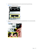
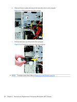
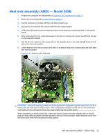
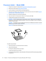
Power Switch/LED Assembly 1. Prepare the computer for disassembly (Preparation for Disassembly on page 3). 2. Remove the access panel (Access Panel on page 4). 3. Lay the computer on its side with the front facing toward you. 4. Remove the front bezel (Front Bezel on page 6). 5. Remove the optical drive (Removing an Optical Drive on page 23). 6. Disconnect the braided cables from the system board. 7. Remove the cable from the clips in the optical drive cage. 8. Press the tabs near the bottom on both sides of the switch holder (1) to disengage it from the chassis, rotate the bottom of the switch upward (2), and then pull it away from the chassis while guiding the wires through the hole in the chassis. Figure 2-44 Removing the power switch To install the power switch/LED assembly, reverse the removal procedures. 32 Chapter 2 Removal and Replacement Procedures Microtower (MT) Chassis
-
 1
1 -
2
-
3
-
4
-
5
-
6
-
7
-
8
-
9
-
10
-
11
-
12
-
13
-
14
-
15
-
16
-
17
-
18
-
19
-
20
-
21
-
22
-
23
-
24
-
25
-
26
-
27
-
28
-
29
-
30
-
31
-
32
-
33
-
34
-
 35
35 -
 36
36 -
 37
37 -
 38
38 -
 39
39 -
 40
40 -
 41
41 -
 42
42 -
 43
43 -
 44
44 -
 45
45 -
46
-
47
-
48
-
49
-
50
-
51
-
52
-
53
-
54
-
55
-
56
-
57
-
58
-
59
-
60
-
61
-
62
-
63
-
64
-
65
-
66
-
67
-
68
-
69
-
70
-
71
-
72
-
73
-
74
-
75
-
76
-
77
-
78
-
79
-
80
-
81
-
82
-
83
-
84
-
85
-
86
-
87
-
88
-
89
-
90
-
91
-
92
-
93
-
94
-
95
-
96
-
97
-
98
-
99
-
100
-
101
-
102
-
103
-
104
-
105
-
106
-
107
-
108
 |
 |
