HP NV517UT Maintenance & Service Guide: Compaq 500B and 505B Minitower Bus - Page 53
System Board
 |
UPC - 884962596715
View all HP NV517UT manuals
Add to My Manuals
Save this manual to your list of manuals |
Page 53 highlights
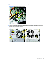
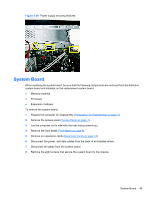
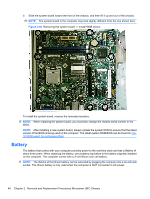
Figure 2-59 Power supply securing features System Board When replacing the system board, be sure that the following components are removed from the defective system board and installed on the replacement system board: ● Memory modules ● Processor ● Expansion modules To remove the system board: 1. Prepare the computer for disassembly (Preparation for Disassembly on page 3). 2. Remove the access panel (Access Panel on page 4). 3. Lay the computer on its side with the rear facing toward you. 4. Remove the front bezel (Front Bezel on page 6). 5. Remove an expansion cards (Expansion Cards on page 12). 6. Disconnect the power, and data cables from the back of all installed drives. 7. Disconnect all cables from the system board. 8. Remove the eight screws that secure the system board to the chassis. System Board 45
-
 1
1 -
2
-
3
-
4
-
5
-
6
-
7
-
8
-
9
-
10
-
11
-
12
-
13
-
14
-
15
-
16
-
17
-
18
-
19
-
20
-
21
-
22
-
23
-
24
-
25
-
26
-
27
-
28
-
29
-
30
-
31
-
32
-
33
-
34
-
35
-
36
-
37
-
38
-
39
-
40
-
41
-
42
-
43
-
44
-
45
-
46
-
47
-
 48
48 -
 49
49 -
 50
50 -
 51
51 -
 52
52 -
 53
53 -
 54
54 -
 55
55 -
 56
56 -
 57
57 -
 58
58 -
59
-
60
-
61
-
62
-
63
-
64
-
65
-
66
-
67
-
68
-
69
-
70
-
71
-
72
-
73
-
74
-
75
-
76
-
77
-
78
-
79
-
80
-
81
-
82
-
83
-
84
-
85
-
86
-
87
-
88
-
89
-
90
-
91
-
92
-
93
-
94
-
95
-
96
-
97
-
98
-
99
-
100
-
101
-
102
-
103
-
104
-
105
-
106
-
107
-
108
 |
 |
