HP Notebook 100 Compaq Armada 100S and Notebook 100 Series Maintenance and Ser - Page 86
Setting the Display DIP Switches
 |
View all HP Notebook 100 manuals
Add to My Manuals
Save this manual to your list of manuals |
Page 86 highlights
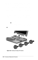
When replacing the system board or display assembly, it is imperative that the DIP switches be set correctly. To set the display DIP switches on the system board, follow these steps: 1. Locate the part number label on the display microphone cable – (Figure 5-28). 2. Part numbers 541566850001/176038-001, 541566931001/ 212897-001, and 413000020183/222715-001 correspond to the 12.1-inch, TFT display assemblies. If these part numbers are on the label, make sure the display DIP switch on the system board is set according to setting —. Part numbers 541566850002/176037-001 and 541566931003/ 216081-001 correspond to two of the 12.1-inch, HPA display assemblies. If these part numbers are on the label, make sure the display DIP switch on the system board is set according to setting ˜. Part number 413000020228/222714-001 corresponds to the third 12.1-inch, HPA display assembly. If this part number is on the label, make sure the display DIP switch on the system board is set according to setting 4. Part number 541566931002/204204-001 corresponds to the 13.3-inch, TFT display assembly. If this is the part number on the label, make sure the display DIP switch on the system board is set according to setting 5. Figure 5-28. Setting the Display DIP Switches 3. After the DIP switch settings have been verified, reassemble the computer. 5-30 Removal and Replacement Procedures
-
 1
1 -
2
-
3
-
4
-
5
-
6
-
7
-
8
-
9
-
10
-
11
-
12
-
13
-
14
-
15
-
16
-
17
-
18
-
19
-
20
-
21
-
22
-
23
-
24
-
25
-
26
-
27
-
28
-
29
-
30
-
31
-
32
-
33
-
34
-
35
-
36
-
37
-
38
-
39
-
40
-
41
-
42
-
43
-
44
-
45
-
46
-
47
-
48
-
49
-
50
-
51
-
52
-
53
-
54
-
55
-
56
-
57
-
58
-
59
-
60
-
61
-
62
-
63
-
64
-
65
-
66
-
67
-
68
-
69
-
70
-
71
-
72
-
73
-
74
-
75
-
76
-
77
-
78
-
79
-
80
-
 81
81 -
 82
82 -
 83
83 -
 84
84 -
 85
85 -
 86
86 -
 87
87 -
 88
88 -
 89
89 -
 90
90 -
 91
91 -
92
-
93
-
94
-
95
-
96
-
97
-
98
-
99
-
100
-
101
-
102
-
103
-
104
-
105
-
106
-
107
-
108
-
109
-
110
 |
 |
