HP OMEN 17-w000 Maintenance & Service Guide: Models with GeForce GTX 1050/ - Page 79
Remove the display assembly
 |
View all HP OMEN 17-w000 manuals
Add to My Manuals
Save this manual to your list of manuals |
Page 79 highlights
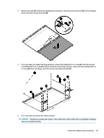
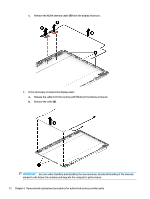
e. SSD (see SSD (M.2) on page 42) f. Disconnect the WLAN cable (see WLAN module on page 45) g. Right speaker (see Right speaker on page 47) h. USB board (see USB board on page 49) i. Fan (see Fan on page 50) j. Heat sink for discrete graphics memory (see Heat sink for discrete graphics memory on page 51) k. Left speaker (see Left speaker on page 53) l. System board (see System board on page 57) Remove the display assembly: 1. Remove the two Phillips screws from the right hinge and the two Phillips screws from the left hinge (1), open the hinges (2) as wide as possible, and then remove the display assembly (3). 2. If it is necessary to replace the display bezel or any of the LED display assembly subcomponents: a. Use a plastic tool to disengage the bezel starting at the top (1), left and right sides (2), and bottom (3). Component replacement procedures 67
-
 1
1 -
2
-
3
-
4
-
5
-
6
-
7
-
8
-
9
-
10
-
11
-
12
-
13
-
14
-
15
-
16
-
17
-
18
-
19
-
20
-
21
-
22
-
23
-
24
-
25
-
26
-
27
-
28
-
29
-
30
-
31
-
32
-
33
-
34
-
35
-
36
-
37
-
38
-
39
-
40
-
41
-
42
-
43
-
44
-
45
-
46
-
47
-
48
-
49
-
50
-
51
-
52
-
53
-
54
-
55
-
56
-
57
-
58
-
59
-
60
-
61
-
62
-
63
-
64
-
65
-
66
-
67
-
68
-
69
-
70
-
71
-
72
-
73
-
 74
74 -
 75
75 -
 76
76 -
 77
77 -
 78
78 -
 79
79 -
 80
80 -
 81
81 -
 82
82 -
 83
83 -
 84
84 -
85
-
86
-
87
-
88
-
89
-
90
-
91
-
92
-
93
-
94
-
95
-
96
-
97
-
98
-
99
-
100
-
101
-
102
-
103
-
104
 |
 |
