HP Pavilion 14-e000 HP Pavillion 14 Notebook PC Maintenance and Service Guide - Page 74
the system board components, it may be necessary to move the heat sink from side to side
 |
View all HP Pavilion 14-e000 manuals
Add to My Manuals
Save this manual to your list of manuals |
Page 74 highlights
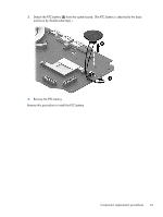
e. Top cover (see Top cover on page 49) f. System board (see System board on page 57) g. Fan (see Fan on page 62) Remove the heat sink: 1. Turn the system board upside down, with the front toward you. NOTE: Steps 2 and 3 apply to computer models equipped with a graphics subsystem with discrete memory. 2. Following the 1 through 7 sequence stamped into the heat sink, loosen the seven captive Phillips screws (1) that secure the heat sink to the system board. 3. Remove the heat sink (2). NOTE: Due to the adhesive quality of the thermal material located between the heat sink and the system board components, it may be necessary to move the heat sink from side to side to detach it. NOTE: Steps 4 and 5 apply to computer models equipped with a graphics subsystem with UMA memory. 4. Following the 1 through 4 sequence stamped into the heat sink, loosen the four captive Phillips screws (1) that secure the heat sink to the system board. 64 Chapter 6 Removal and replacement procedures for Authorized Service Provider parts
-
 1
1 -
2
-
3
-
4
-
5
-
6
-
7
-
8
-
9
-
10
-
11
-
12
-
13
-
14
-
15
-
16
-
17
-
18
-
19
-
20
-
21
-
22
-
23
-
24
-
25
-
26
-
27
-
28
-
29
-
30
-
31
-
32
-
33
-
34
-
35
-
36
-
37
-
38
-
39
-
40
-
41
-
42
-
43
-
44
-
45
-
46
-
47
-
48
-
49
-
50
-
51
-
52
-
53
-
54
-
55
-
56
-
57
-
58
-
59
-
60
-
61
-
62
-
63
-
64
-
65
-
66
-
67
-
68
-
 69
69 -
 70
70 -
 71
71 -
 72
72 -
 73
73 -
 74
74 -
 75
75 -
 76
76 -
 77
77 -
 78
78 -
 79
79 -
80
-
81
-
82
-
83
-
84
-
85
-
86
-
87
-
88
-
89
-
90
-
91
-
92
-
93
-
94
-
95
-
96
-
97
-
98
-
99
-
100
-
101
-
102
-
103
-
104
-
105
-
106
-
107
-
108
-
109
-
110
-
111
-
112
-
113
-
114
 |
 |
