HP Pavilion 14-e000 HP Pavillion 14 Notebook PC Maintenance and Service Guide - Page 91
CAUTION, and swing it up and forward until it rests upside
 |
View all HP Pavilion 14-e000 manuals
Add to My Manuals
Save this manual to your list of manuals |
Page 91 highlights
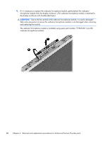
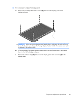
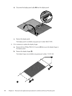
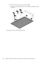
5. If it is necessary to replace the display panel: a. Remove the six Phillips PM2.5×4.5 screws (2) that secure the display panel to the display enclosure. CAUTION: Before turning the display panel upside down, make sure the work surface is clear of tools, screws, and any other foreign objects. Failure to follow this caution can result in damage to the display panel. b. Lift the top edge of the display panel (1) and swing it up and forward until it rests upside down in front of the display enclosure. c. Release the adhesive strip (2) that secures the display panel cable connector (3) to the display panel. Component replacement procedures 81
-
 1
1 -
2
-
3
-
4
-
5
-
6
-
7
-
8
-
9
-
10
-
11
-
12
-
13
-
14
-
15
-
16
-
17
-
18
-
19
-
20
-
21
-
22
-
23
-
24
-
25
-
26
-
27
-
28
-
29
-
30
-
31
-
32
-
33
-
34
-
35
-
36
-
37
-
38
-
39
-
40
-
41
-
42
-
43
-
44
-
45
-
46
-
47
-
48
-
49
-
50
-
51
-
52
-
53
-
54
-
55
-
56
-
57
-
58
-
59
-
60
-
61
-
62
-
63
-
64
-
65
-
66
-
67
-
68
-
69
-
70
-
71
-
72
-
73
-
74
-
75
-
76
-
77
-
78
-
79
-
80
-
81
-
82
-
83
-
84
-
85
-
 86
86 -
 87
87 -
 88
88 -
 89
89 -
 90
90 -
 91
91 -
 92
92 -
 93
93 -
 94
94 -
 95
95 -
 96
96 -
97
-
98
-
99
-
100
-
101
-
102
-
103
-
104
-
105
-
106
-
107
-
108
-
109
-
110
-
111
-
112
-
113
-
114
 |
 |

5.
If it is necessary to replace the display panel:
a.
Remove the six Phillips PM2.5×4.5 screws
(2)
that secure the display panel to the
display enclosure.
CAUTION:
Before turning the display panel upside down, make sure the work surface is
clear of tools, screws, and any other foreign objects. Failure to follow this caution can result
in damage to the display panel.
b.
Lift the top edge of the display panel
(1)
and swing it up and forward until it rests upside
down in front of the display enclosure.
c.
Release the adhesive strip
(2)
that secures the display panel cable connector
(3)
to the
display panel.
Component replacement procedures
81